21. Inter Cam Box Repairs
The single knocker cam box, as used on all the 'cammy' models from 1931 to 1958, is a poor design, is prone to break, is difficult to work on and it leaks oil like a primary chain case! Why Norton persisted with it for over 25 years is anybody's guess? Most of the research and development was done on the double knockers, although in 1935 the works machines sported an enclosed cam box.
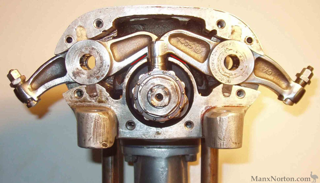
The most common fault with the cam box shell, is a broken tunnel. This is usually due to excessive wear at the rocker pad ends, which in turn means that the underside of the rocker hits the tunnel, causing the latter to break up (marked with a red line in the photograph). The purpose of the tunnel is to keep as much oil at the cam to rocker pad interface as possible and when it is broken, the oil loss from the cam box becomes so bad that most of the riders bottom half and the machines rear end are drenched in the stuff! The tunnel can also be damaged by inexperienced mechanics (bl**dy idiots) who do not know how to remove cams and replace pads.
The next most common fault with the shell is a broken 'leg' due to someone failing to check that all four mounting points for the cam box are perfectly horizontal and square (extended head bolts on the Models 30 and 40, individual spacers on CS1 and CJ).
As in all alloy (or magnesium) castings, threads are often damaged and mating surfaces scored by careless use of the wrong tool!
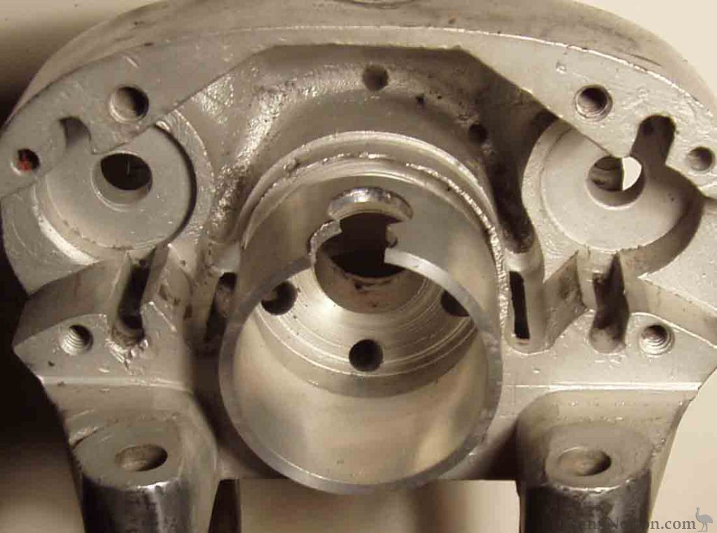
To repair the tunnel, I machine away the broken item so that I am left with a cam box minus its tunnel. I then make a new tunnel from a piece of alloy tube (2.125 inch o.d.) and use Araldite and a 2BA countersunk screw to fix it in place (see pictures). There is more than one way to machine the cambox; spin it and hold the tool or viscera-versa! Watch How I do it!
MVI_cambox.avi Video missing
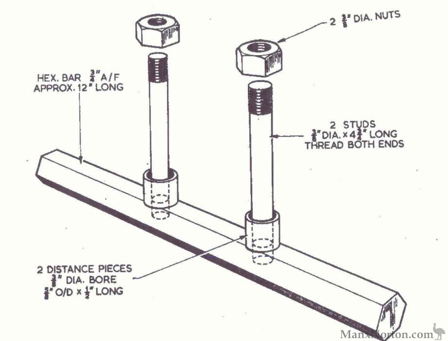
When working on the cambox, I use a variety of special tools and jigs. The simplest 'holding jig', taken from Garratt, can be easily made from a six inch length of hexagonal bar and two 3/8 inch studs. It makes life very much easier. Being hexagonal, the jig can be turned round to work on both sides of the cambox, tilted at a convenient 30 degrees.
Once the cam box shell is perfect, then all the other components can be repaired and rebuilt. It can take a very long time to do all this work and it would take me even longer to write a manual on SOHC cam box re-building! My advice is to NOT do this work unless you have someone with previous experience to show you how. There are many potential traps!
Inlet Valve Opens 57/58 BTDC
Inlet Valve Closes 60 ABDC
Exh Valve Opens 85 BBDC
Exh Valve Closes 42/43 ATDC
This is for Mega or open pipe. With silencer retard inlet by 10 degrees, ie 47/70
These timing figures can only be achieved when there is no wear to the cams, or rocker pads. For timing the cams from scratch the following procedure should be adopted:
Exh No. 5 Inlet No. 1
Exh No. 6 Inlet No. 2
Exh No. 7 Inlet No. 3
10.Good luck!
Norton International cams
INLET EXHAUST MODEL
1932 E41.33 E41.34 40
1933 52.40 52.39 30
1937-39 63.92 63.93 C.S.1.
1937 68.93 E63.87 30
1939 39.40 39.39 40M
1948-52 & EARLIER? 62.12 62.13 30
1946-49 & EARLIER? 115.87 115.88 30M
1953-58 64.66 63.89 40M
77.63 40
1937 WORKS ENCLOSED C/BOX 4IN 4E 30M
These numbers probably mean something, but I have yet to break the code!
You would have thought that they may correspond to the cam timing, but they do not!
Anybody know the answer?