Work for the alternator project was done during the winter of 2002-2003.
Phil Hitchcock has responded to numerous requests to make SOMETHING available for riders who wish to use their Bevel Drive Ducatis without running a "battery recharge required after use" electrical system. He now has a modern rotor and upgraded electrical system available for sale on his website.
Follow this link for further information: Phil's
Alternator Conversion
"The alternator worked fine for most Europeans, who were used to running their motorcycles in the upper half of the RPM range (4 grand to 8 grand). On the other hand, North Americans, more used to the low-revving Harley engines, ran the engine in the lower half of the RPM range, so the battery never really got charged up."
A few measurements taken in the summer of 1998 on my stock 1973 750 Sport showed that the alternator battery didn't start charging until the tach was in the 3000 to 3500 RPM range. I'd installed a Dyna electronic ignition some years before, and aftermarket ignition coils ( 5 ohm primary resistance each ) to clean up the notoriously bad OEM ignition coils. The ignition coil problem was documented in Cycle magazine in an article by Gordon Jennings in 1977. A scanned version of the CYCLE article can be found online at the Ducatimecannica website.
The voltage readings explained a number of problems I'd had over the
years with low battery voltage and spark plug fouling issues. It was clear
I'd have to fix the alternator/battery charging problem if I wanted a reliable
ignition system.
The mathematic equation of the process gives some clues as to where we can find ways to improve the alternator output. The equation can be expressed as:
where E is the electromotive force in Volts, N is the number of turns in the coil and ∂Φ/∂t is the rate of change of the magnetic flux. Thus, if we can increase the speed, or the magnetic flux (stronger magnets, or a smaller rotor to stator gap, or more magnets in the rotor), OR the number of turns on the coil (stator, in this case) we will increase the alternator output!
Just to be clear in the following discussions, the rotor is the
part of the alternator that rotates. In the case of the Roundcase bevel
twin, it consists of a hub with 14 permanent magnets embedded in it. The
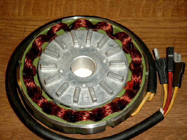
stator
is the part that remains static, in this case the alternator coils mounted
in the right hand engine cover.
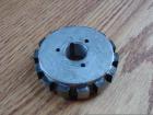
The Roundcase Bevel Rotor |
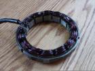
The Roundcase Bevel Stator |
Here I need to mention some of the constraints - the engine speed (RPM) is directly under the user's control - you can run the engine at high RPM, or at low RPM by simply changing gears and twisting the throttle! In general, if you just keep the engine speed above 4000 RPM, you'll probably be charging the battery. If this works for you, and you don't have to idle at stoplights, you probably don't need the alternator conversion!
Some people have had their stator rewound to increase the number of turns on the coil, which will also increase the alternator output. This might work for you if you still have a rotor with strong magnets. However, this may also require modifications to the engine case, since the size of the stator typically increases when a stator with more turns on the coil is fitted.
The original alternator conversion information I had was from Kent Jornevall and Brad Turner, and they used both the ST2 rotor and stator. They both reported some slight modifications and/or machining done to the engine case to use the larger ST2 stator coil. My experiments indicated that the ST2 stator coil is probably not required, depending on your system load. However, there may be a few more windings on the ST2 stator coil, which would increase the output even more, for those that feel they need more (electrical) power!
I should mention here that decreasing the air gap (effectively, the clearance between the rotor and stator) is a possibility, but it's one I DON'T recommend, since there's not a lot of clearance there to begin with, and the tolerances were probably chosen by the original designers to squeeze out as much benefit here as possible, without shredding the engine. The improvement probably isn't as great as the other methods, in any case.
The final opportunity for improvement is to increase the magnetic field strength. This can be done by remagnetizing the rotor magnets, building a new rotor with more magnets, or using better magnets.
I decided to minimize engine mods and allow for restoring my engine
to stock, should I ever have a reason to do so. I used a new rotor with
better magnets (and also because I had one close at hand!).
Phil Hitchcock offers a rewound alternator for sale through his website
Road
and Race. Look under the "Electrical Repairs" section...
I happened to have one of these rotors available due to some of the alternator problems that were characteristic of the 1998 North America ST-2 model. I was on my third alternator when I finally sold my ST-2!
Peter Koren reports on other rotor alternatives:
"There are definitely some suitable rotors out there that look identical to the early ST2. Some 888 Corsa's used them, and DucatiPerformance list a lightweight 180w two wire narrow alternator kit for Monsters."Three wire versions also come up like this one from Germany.
"I got a rotor like these and it seems roughly twice as strong as roundcase rotor based on ability to lift a bag of small bolts!"
"The trickiest part is buying the rotor on it's own, everyone wants to sell the complete alternator. It's maybe not as powerful as the ST2 item, but more readily available and a certain upgrade from tired old roundcase rotor."
I measured carefully how far out of the case the old rotor was before I removed it. The old rotor had a thick steel slotted washer behind it which sat in a recess on the back of the original rotor. The ST2 rotor did not have a recess on the back (finned side), hence I didn't use the washer with the new rotor. Once mounted on the end of the crank, the outer surface of the ST2 was within a fraction of a millimeter of where the old rotor was. There was an important difference, however, in that the old rotor had magnets that protruded from the rotor body whereas the magnets on the ST2 rotor are flush with the rotor body, making the ST2 rotor body effectively larger in diameter. This is important since when the rotor sits in the stator, the new rotor protruded beyond the coils and can make contact with the three soldered connections to the stator. Those connections needed to be ground down a bit to be flush with the stator coil surfaces to prevent the rotor from making contact. I hope this isn't too confusing, but once you look at it, it's obvious.I've recently heard that late model Monster 600/750 series engines may use a similar rotor as the 1998 ST-2, but I've no confirmation of this. If someone can provide further information about these possible replacements, I'd be glad to post the information here!
George Betzhold provided a dimensioned drawing of the original roundcase
rotor for reference.
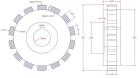
Dimensioned Original Rotor |
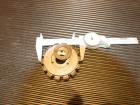
Meanwhile, here's the rotor dimensions that I measured on the rotor I used:
Rotor thickness: 20.8 mm (NOT including the fins)
Rotor Diameter:  76.42 mm +/- 0.02mm
I mounted the reclaimed ST-2 rotor directly on the end of the crankshaft where the original rotor used to be mounted. I mounted the rotor with the "fins" facing inside, towards the engine. The pictures below show a better view of this than my description.
Original Rotor |
ST2 Rotor 1 |
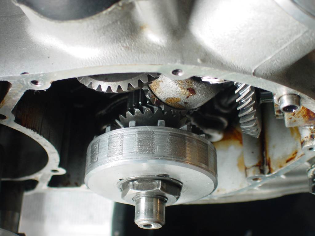
ST2 Rotor 2 |
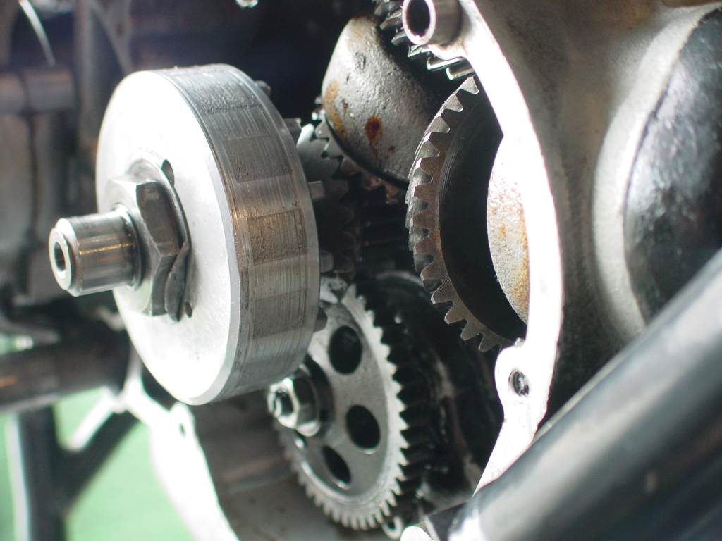
ST2 Rotor 3 |
Now, some information about the cost of this conversion...
Originally, I believe the ST-2 alternators cost around $300 US. I last had to buy a replacement (out of warranty) alternator for my ST-2 in late 2001, and at that time the price I was quoted through the local Ducati Dealer was ~ $1050! I managed to obtain one from another source, but still paid about $850 for the unit!
For this reason, I recommend you look for a used or alternative alternator
rotor replacement if you are thinking of doing this, or a similar, conversion!
I believe the difference in the alternator output is due to the use of rare earth magnets in the late model rotor (not readily available in 1973!) and the fact that the original rotor magnets probably gradually demagnetized over the more than 30 years since this motorcycle was manufactured.
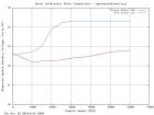
George Betzhold took measurements of the system DC voltage on his Sport
with the original and the new ST2 rotors. This is the DC voltage at the
OUTPUT
side of the rectifier/regulator black box. The center graph below shows
these measurements with much improved battery charging. It shows
the system is now able to keep up with the current draw from just above
idle speed.
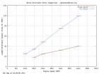
Alternator Output |
System DC Voltage |
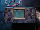
Waveform View |
The third picture is a photo of the alternator voltage waveform as seen at the regulator input, with the ST2 rotor in place. If you examine the waveform carefully, it's apparent that the (original, stock) regulator is only conducting for about 50% of the time at this low RPM! It's no wonder the stock arrangement couldn't keep the battery charged... The measurement conditions for this photo were:
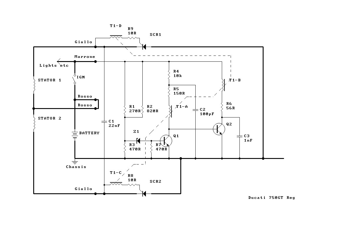
Engine RPM:      1200 on Tach; actually ~ 860 RPM indicated on oscilloscope
Voltage Scale:   10 Volts per Division, AC coupled
Battery Voltage: 12.1 Volts
Time Scale:      2 milliseconds per division
Rotor Config:    14 separate magnets ( *7 effective RPM multiplier )
The measurements were taken from ground to each side of the alternator output. Note that the original alternator is a two phase alternator with a common center tap (three connections) as shown in the regulator schematic.
Items to change :Brad Turner reports on the machining:
Rotor :
The rotor needs to be assembled towards the bevel gear with its fins to the cover side and without any washer inside it. A small machining needs to be done, a groove diameter 31mm and 2mm deep to get it 2mm more towards the bevel gear.Stator winding :
Fits direct to the cover, but as you fit it you will see that it sticks up about 4-5 mm from the cover so that its not flush to the cover and the screws wont hold it. I will machine an aluminum ring that will work like a spacer on which I can put the M6 bolts to keep it together.Its actually that simple !!
All checked with plastelina to see too that all gears are free.
I am using an German after market regulator, but i think i will see what can be used as i have a 3Ah battery.
The machining done was I believe to the rotor mount which had to be recessed about 0.005 inches. Also, the three mounting tabs have standoff rods welded to them to account for the thicker stator. Don't think there was any machining to the case covers; did have to recess one of the reinforcing webs to install the hydraulic clutch though. So far so good...
Some may recall I threatened to report on what happenes if you change the way the standard 3 lead alternator is wired...First off I took some measurements of alternator output using different regulators and methods of connection, then I changed the way the 2 sets of alternator coils are wired and measured the output again.
Conclusion is that the rewired configuration does produce more power - putting it another way, it balances the load at lower RPM.
Measurement of output is a little bit of a challenge, as it's the max capability at any rpm that needs to be measured - and the regulator may be doing it's job and reducing the output depending on the battery state. So I recorded the rpm at which various loads were balanced.
I put a 0.022 ohm resistor between the battery + terminal and the wiring harness, and put a digital voltmeter across that, so 0 volts => alternator output was balancing the load. Biggest inaccuracy was measuring rpm with a (new) smiths tacho.
I took measurements of rpm needed for load balance with just the RITA ignition (with 3 ohm twin output Dyna coil), ignition plus side/pilot/instrument(side) lights, ignition plus side lights and 55W dip, and finally ignition plus side lights and 100W main.
First configuration was the stock set-up and 3 lead regulator
load                  rpm for balance
--------------------------------------
RITA                    2,250
RITA + side             2,400
RITA + side + 55W       3,250
RITA + side+ 100W       3,800
Next I replaced the regulator with 2 diodes to see if the regulator was losing any power - red wire left connected to + and white wires connected via diodes to ground. Results were identical, so the stock regulator works just fine.Next configuration was to disconnect the red wire (centre tap) and to connect the white wires to the AC terminals of a bridge rectifier. As expected, the output is much higher at low rpm, but it never balances the higher load.
load                 rpm for balance
--------------------------------------
RITA                    1,400
RITA + side             1,700
RITA + side + 55W       4,000
RITA + side+ 100W       N/A
Finally I reconnected the alternator leads at the alternator, and i guess this needs a bit more explanation.Here's the stock arrangement: ____white / \ / \____red___ to +ve / \ / \____whiteThe outputs of the white leads are out of phase - when one goes positive, the other goes negative. Stock regulator therefore uses the output of only one of the white wires at any point in time: they take it in turns to contribute current. (and just to confuse, the regulator does this by connecting them to ground).If you take the stator out of the cover, you'll see three terminals to which the solid copper wire of the coils and the output wires are soldered. I unsoldered the centre terminal and took one of the solid copper wires off and connected it to the end terminal - move the one that measures open circuit to the terminal you're going to solder it to. I reconnected the red wire to the end one with both sets of coils attached, and the loose white one to the middle.
Before:
 ____|--------white
/
\
/
\____
 ____|--------red
/
\
/
\____|--------white


After:

 ____|--------white
/
\
/
\
|    ____|-------white
|   /
|   \
|   /
|   \____
|________|-------red
This arrangement has both coils contributing IN phase: thay both go positive at the same time. If both coils had the same number of turns you could connect both white wires together and use a 2 lead regulator - I'll check some time. Not being sure, I kept the wires separate and used a 3 phase 400V 35A bridge rectifier (they have 3 AC terminals and contain 3 pairs of diodes) I put a Lucas zener diode in as a regulator. Rectifier and zener (on a heatsink) are mounted on an ally plate where the rear air filter used to be.load rpm for balance -------------------------------------- RITA 2,100 RITA + side 2,300 RITA + side + 55W 3,100 RITA + side + 100W 3,400So, it'll run a 100W headlight at 400rpm less. May not sound much, but it's quite a lot in the context of the rev range used in town or traffic. I'm confident I'll now be able to use an 80/100 headlight and am leaving the alternator like thisI measured the charge rate at 4000 rpm with main beam at about 1.5A and when I get time I'll take some output current measurements and compare with the data in the workshop manual for the stock system.
If you're suffering from low battery voltage issues on your Bevel Ducati roundcase engine, find a late model alternator rotor that fits in place of the original and use it to replace the stock rotor. Leave the original regulator and stator coil in place, and don't hook up any additional lights or devices to the electrical system.
Remember, you do this at your OWN risk!!!
Rene & Sue Waters  - for maintaining the ducatimeccanica website!
Gene Rankin, et al - for maintaining the Bevelheads list!
Kent Jornevall  - the originator of the alternator swap idea, as far as I can tell!
Brad Turner     - for information about his conversion.
Malcolm Moore   - for the reverse engineered Regulator Schematic.
James de Raeve  - for rectifier and alternator wiring information.
Joe Tokarz      - for discussions and information on re-magnetizing rotors.
George Betzhold - for dimensioned drawing of rotor and voltage measurements.
Peter Koren     - for information on alternative rotor sources.
Corey Levinson  - for information on holes in earlier versions of this documentation.
In regard to Ducatis vs. women, it has been said, "One is a sexy thing that you've just got to ride, even if it breaks down a lot, costs a lot of money, and will probably try to kill you...." ....however, nowadays I can't seem to remember which one is which. - Peer Landa