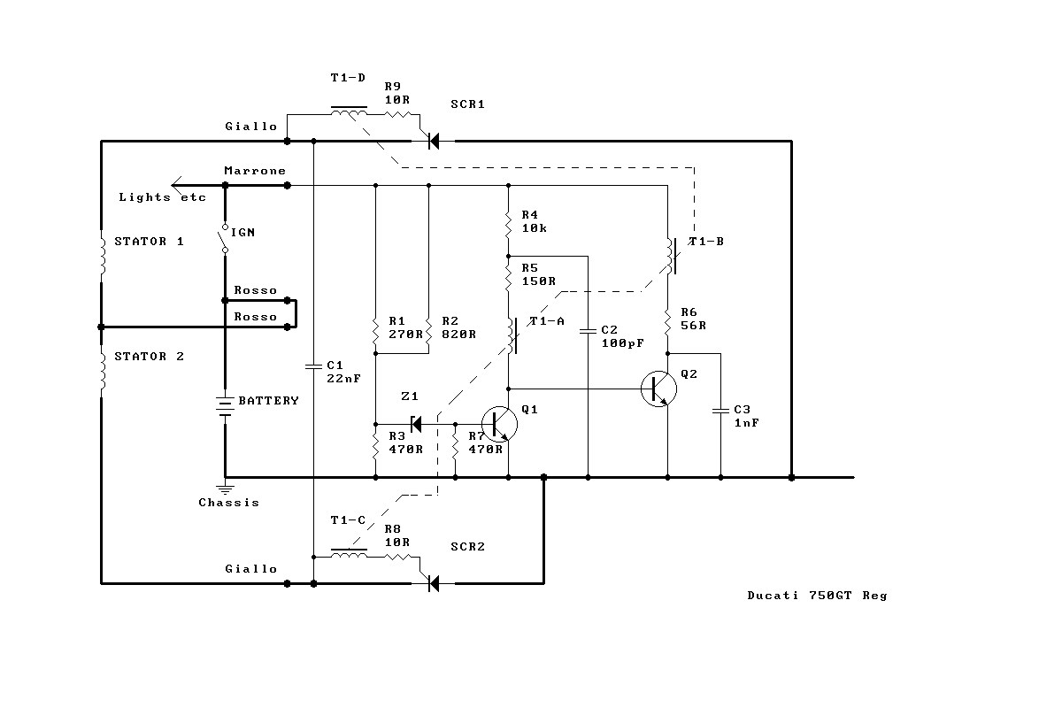
Regulator Schematic |
|
Regulator Schematic |
The Ducati 200W units are 2 lead single phase and will work just fine with your regulators, but after market regulators do not work well on the earlier 150W 3 lead alternators fitted to 750 roundcases and a few early 860 squarecases.This is because the 3 lead alternator is NOT 3 phase. Ducati were real cheapskates, and it was 1970 when SCRs were expensive, so they designed a regulator with two SCRs, cathode to case mounted directly on the heat sink. To feed this they designed an alternator with a single winding plus centre tap. The centre tap goes to battery +ve and the two ends of the winding then get grounded alternately through the regulator. Dumb design, half wave rectified, but the regulator was cheap!
If you connect the three leads to a 3 phase regulator then the red centre tap lead will always be at a voltage half way between the 2 yellows - and will contribute sod all.
Connected to a 2 phase regulator the 2 yellows will give all they've got, which is fine at idle and up to a couple of thousand rpm, but they hit a limit because the resistance of the windings is way too high. The measurements I've taken show the circuit will not run ignition and 55W headlight at ANY rpm (I took it to 7000).
Fixes are:
a) replace the regulator with a rebuilt one of the same configuration (Syd's cycles do one), or
b) use 2 diodes from a bridge to ground as a rectifier and a zener to regulate
c) invert the polarity of one half of the winding and use the two halves in parallel rather than series into any 2 phase regulator (I use a rectifier/zener and it's arguable that the 2 windings won't be completely in phase so a 3 phase unit would be a better choice), or
d) replace the alternator with a later (ST2) unit entirely.
Option c) runs a 100W headlight and ignition quite happily - and you can see at night!
Bottom line: do not bother with after market regulators on a roundcase with a stock alternator - it WILL be worse than stock and it isn't the fault of the regulator it's just a weird way to wire an alternator that no rational regulator designer would have thought of doing in the last 25 years!
Testing and tuning up my '74 GT's charging system revealed the following.No load alternator output is about 32 to 40vac
Charge balance should be about 1500 to 2000 rpm with ignition only (depending on type of coils) and about 3000 with ignition and lights. That's about as good as it gets with stock rotor and stator.
Measure balance with a low resistance resistor ( about .02 ohms but actual value is not important unless current measurements are calculated) in series with the positive battery wire. Connect digital voltmeter across the resistor. Balance is at zero. Change current can be calculated  See this site if  you've misplaced your Electronics 101 text book. Electronics Info Page
The SCR diodes in the regulator can fail  for a variety of reasons. Age, vibration, etc. These devices were somewhat exotic 25 years ago. They can be tested for leakage / open / short with an ohm meter.  The PDF is here: SCR documentation
I found one of mine "leaky"Â and replaced both. A direct replacement is NTE 5514. Â The PDF spec sheet is here: NTE 5514 Spec Sheet. Price is about $6.00 each. Go to main page to find a distributor near you.
Drive the old SCR's out with a flat punch. I took the opportunity to bead blast the entire cast aluminum box to remove all oxide and mineral deposit buildup. ( over the years the box got wet and stayed wet.) Install the new SCR's by warming up the box to relieve the interference fit. Gently push in the new SCR's. I used a appropriate fitting socket to not bend the contacts. Re-wire and refresh all solder connections. Scotch-Bright all the slip connectors.
The SCR trigger circuit is completely encapsulated so there's no repair of it. I'd like to see the circuit diagram because that's the only thing we can't diddle with to improve charging. My hunch is that if the trigger point were lowered, charging may improve some. Of course the rotor magnets are not strong like more modern applications. I looked into re-magnetizing but in the end I don't think that would yield the desired results. The magnetic material used just doesn't have enough Gauss. ( I think that's correct term)
Hope this helps.
Best Regards from Texas, Joe
The interrupter type of regulator operates as a switch to apply the rectified alternator voltage to the battery in pulses only when the battery voltage drops low enough to require it, and effectively opens the switch so the alternator runs with no load when the battery is fully charged.
Most modern motorcycles (from 1990 on) use a shunt type of regulator. The shunt regulator operates as a variable load, and dumps current through this load to keep the rectified voltage down to a tolerable level. The shunt regulator converts the excess voltage & current directly to heat, and requires a good heat sink to dissipate the heat without damage to the regulator. This arrangement puts more strain on the stator windings at higher RPM, since they're flowing current continuously, and always heating.
The original series regulator is a fairly effective regulator for the system, but does suffer from lower charging current at low RPM. However, it doesn't convert the excess voltage and current to heat, so it doesn't place a heating load on the stator coils, nor does it require as much heat sinking.
The downside of the shunt regulator is that it will result in higher open circuit voltages at the stator coil terminals, which could lead to insulation breakdown in the stator. It can also generate microsecond-long voltage spikes on the DC side of the system, which could be a problem if you're running any modern electronic devices (such as a cell phone or radar detector) which are not very tolerant over voltage spikes.
Resistive loads, such as an electric vest or higher power headlights, aren't normally affected by these spikes. In the days of points and coil ignition systems, power supply voltage spikes were never an issue. However, once micro-processor controlled fuel injectors were introduced, the power supply spikes could easily kill or reset the fuel injection computer... Thus, the alternator reliability now suffers to enhance the EFI computer reliability.
The original Rita and Dyna after market electronic ignitions were designed
to run with the original charging system and are very tolerant of the voltage
spikes.
Malcolm Moore - for the reverse engineered Regulator Schematic.
James de Raeve  - for information on alternator capacity.
Joe Tokarz - for discussions and information on re-magnetizing rotors.

Rene & Sue Waters  - for maintaining the ducatimeccanica website!
Gene Rankin, et al - for maintaining the Bevelheads list!
index.html
Created with Xemacs - Last modified: Tue Jun
12 19:41:55 MDT 2007
Regulator Schematic Copyright © 2002 Malcolm Moore
Copyright © 2004 Willy Gonnason