Springfield Place, Harnell Lane, Coventry.
Late in 1911 a machine appeared that was different from the rest. It had a pressure lubrication system with a gear pump submerged in the oil in the sump. Both main bearings, the big end and the gudgeon pin were force fed in an era when most still relied on a hand pump, sight bowl and drip feed. Other 496cc engine details were a separate cylinder head, both it and the barrel being held by three long bolts, and a front-mounted magneto. It also had Druid forks and direct drive by belt or optionally a Sturmey-Archer hub gear with clutch.
The machine carried on in that form until 1913.
The founders of Wartnaby & Draper were William Thomas Wade Wartnaby (1885-1925) of Market Harbourough and Alick Darby Draper (b.1884-1981) of Hemel Hempstead.
Both attended Rugby School around 1900, and during their tenure developed an interest in engineering. Harry Ricardo was also a pupil at Rugby School in those years.
During the war William Wartnaby served in the Royal Navy until August 1916, he then transferred to the Royal Flying Corps. He died in 1925.
Alick Draper served with the Army Service Corps and attained the rank of Captain. In 1928 he applied for admission to The Institution of Automobile Engineers; the proposer for his application was Harry Ricardo.
Valve side of the W.D. power plant, showing the oil sump at bottom of crank case
A New Model with Forced Lubrication to all Bearings.
THE W.D. motor bicycle is the joint production of two engineers named Wartnaby and Draper, who are enthusiastic motor cyclists. For some considerable time they have collaborated to design an engine for motor cycles dispensing with splash lubrication.
So far as motor cycle engines are concerned, the pressure feed to all bearings is a new method of lubrication, but outwardly the engine does not differ very much from ordinary types with the exception that the crank case is enlarged at the base to provide a sump for the oil and a place for the oil pump to work in. As the patentees pointed out, many will doubtless ask, "Why introduce the complication of forced lubrication?" In their opinion, and we confirm it, there is no objection whatever to complication, per se, provided it gives no trouble.
Is Forced Lubrication Wanted?
When we saw the machine last week and discussed the question with Messrs. Wartnaby and Draper they mentioned, what is, we think, quite correct, viz., that forced lubrication is more necessary on motor cycle engines than on car engines owing to the limited space available for bearings on the former type, and also the fact that in nearly all cases the crank end does not dip in oil, neither can it be made to do so where inside flywheels are fitted without a central trough for lubricating oil, for which there is hardly space in the majority of motor cycle crank cases.
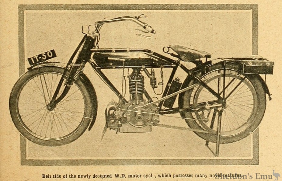
The chief claims for forced lubrication are long life, maintenance of power and efficiency for long periods, sweetness and silence of running due to cushion of oil specially forced into the working surfaces, and no necessity to remember when to lubricate, as the sump holds sufficient oil for over 200 miles. The machine, which is on view at the Service Co.'s stand at Olympia this week, is illustrated' herewith.
Details of the Engine.
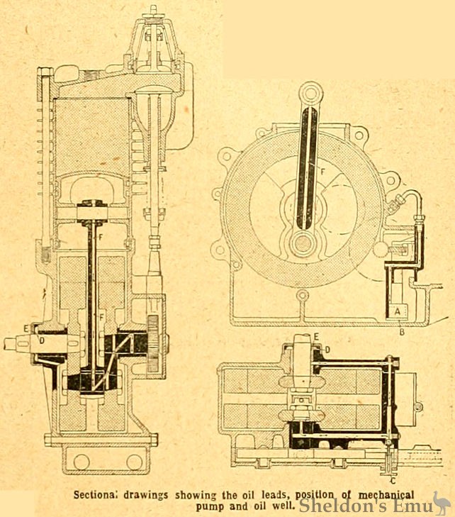
Reference to the line drawings will show the following departures in the construction of the engine. The crank case is cast in one piece, and is provided with a cover plate at one side ; this prevents oil leakage at the joints, and also facilitates the construction where the oil pump has to work. This latter is driven by a skew gear, and the pump spindle rotates vertically, the two small gear wheels of the Albany type pump being, of course, at the base of the sump and running constantly in oil.
The oil passes through a filter A at the base of the pump B, and so on to the pressure regulator C, which is a valve on the side of the crank case adjustable from the outside, and by means of which the pressure can be regulated to give exactly the right amount of lubricant without leakage through excess. From the pressure valve the oil passes into the leads, which are cast in the crank case and lid, and branches off on each side through other leads as marked by indicating arrows to both the crankshaft main bearings. These bearings are provided with an oil ring D which throws the superfluous oil off on to a fixed ring E on the cap of the boss. Oil flung off from these points falls into recesses in the caps and then through holes bored in the aluminium bosses of "the crank case back to the sump.
Forced Feed up the Connecting Rod.
The lead to the crank pin bearing will be clearly seen in the line sketches. The oil passes from the right hand main bearing to the big end through the hollow crankshaft, and then up a pipe F securely attached to the connecting rod ; the ends of the pipe fit in recesses at top and bottom of the connecting rod, and in addition the pipe is further held by the small metal straps shown. The pipe being recessed in the rod cannot come away through vibration. When the oil has passed up this pipe to the gudgeon pin bearing the surplus falls out on the flywheels and is thrown up the cylinder to lubricate the piston. It will be noticed that the flywheels do not revolve in oil, therefore the friction usually occasioned by the film of oil between the crank case and the rims of the flywheels is avoided. A vacuum valve (not shown) is provided on the side of the crank case. This is of the swinging disc valve type, but as_ the crank case is a very large size it is claimed to be practically free from vacuum.
In addition to the supply of oil carried in the sump, which is sufficient for 200 miles or more, a tank (see photograph of complete machine) is placed behind the seat tube fitted with an ordinary pattern hand pump. The patentees recommend when starting out that the amount of oil should be verified by opening the trial tap in the side of the sump. If oil issues from this tap there is a sufficient quantity in the sump, and no more need be pumped in from the reservoir, but if this tap should be dry oil must be injected by the hand pump until it runs out at the trial tap. In ordinary daily use all that is necessary is to verify the level of the oil when starting out for a run ; afterwards the lubrication looks after itself.
Other Features of the Engine.
Turning to the other features of the engine, it will be noted that the combustion head is separate from the cylinder, and that both are held down to the crank case by three bolts bedded in the aluminium crank case. The valves are of particularly large diameter (40 mm.), the inlet being situated over the exhaust and mechanically operated. We had an opportunity of examining one of these machines just before the Show opened, as it was being assembled for exhibition, and were interested to note that everything had been so carefully thought out on paper that the engine parts fitted together without the slightest hitch.
The crank case, instead of being made in two halves as usual, is cast almost in one piece with the sump, one side. only being detachable.
This machine, the frame and other details of which are excellently constructed, is being made in temporary works at Coventry, and for the present communications regarding it may be sent to W. and D. Motors, 21, Coundon Road, Coventry.
The Motor Cycle November 23rd, 1911. Page 1305
Sources: