Converting Cam & Idler Bushes to Needle Roller Bearings
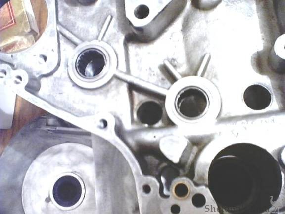
To convert cam and idler bushes to needle roller bearing. You will need 5 Torrington n/roller bearings 4 of which will be 27 OD 19 ID and 20 mm long. 1 will be 27OD, 19ID and 15 mm Long. The short one will be in the inner timing cover. The reason Metric bearings are used is this? The cam and idler shafts are exactly 19 mm so the metric bearing will give correct running clearances. If an Imperial N/roller bearing is used you will have .002" to much clearance because the shaft sizes are 19mm not ¾". The bearing holes are to be bored size for size and bearings fitted with Locktite.
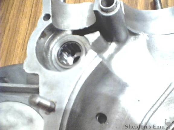
The drive side C/C is bolted to the Mill bed, primary side down. The mating face is dialed in true then the cam bush hole is dialed in. (all bushes have been removed from crankcase.) The cam position is bored size for size with the bearing. The bearing when fitted sits proud of the face by ½ mm and a spacer is fitted behind the bearing to achieve this. All studs are fitted to the C/C and the 2 halves are bolted together. Care is taken that the case halves are true where the barrels fit on.
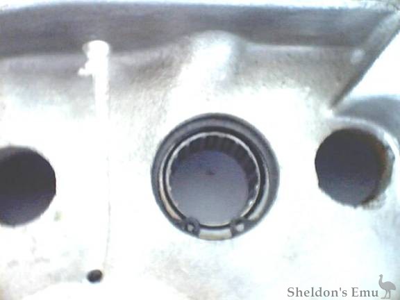
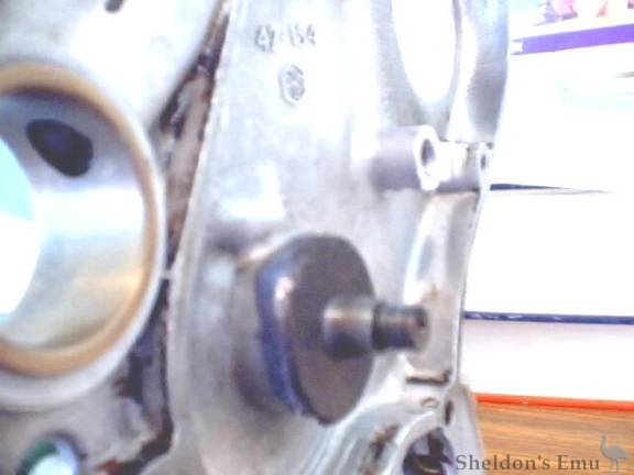
The cam position is then bored size for size with the bearings. The inner timing cover is then bolted into position and a cut is taken through the breather position to make sure every thing is in line. A bronze bush is fitted in this position. I used an old front fork bush and machined the hole to give .002" interference on the bush. (After the bush is fitted I drilled the breather passage hole through it). The clearance on the breather is .004".
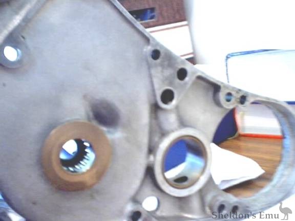
The inner timing cover is then removed and you dial in the idler position in the C/C. Again bore size for size, refit the inner timing cover and bore it to. The oil holes that fed the original bushes will not line up with oil groove in the bearings so a small channel 2 mm wide 1 mm deep is ground in the C/C from the hole to meet the groove. A circlip groove is placed in the C/C idler position behind the bearing to prevent it walking into the crank should it become loose.
The bearing when fitted should be proud of the face by ½ mm. This distance is also used for the T/S crankcase cam bearing position.
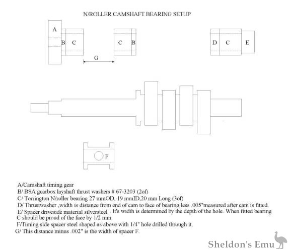
I use a hardened layshaft thrust washer from a BSA A10 gearbox Part# 67-3203 (3 will be required) 1 each behind the timing gears and 1 inside on the camshaft. After boring your cam and idler positions you must fit thrust washers B and bearings C onto camshaft. Fit timing gear and tighten every thing up. Measure the distance G and subtract .002"and you will have the width of spacer F. Fit the bearings and spacer into the C/C remembering the bearing must sit proud of the face by ½ mm. Assemble the camshaft not forgetting thrust washers B and timing gear, fully tightened. You should have .002" end float.
Measure the depth of cam hole drive side, to work out the width of spacer E that will leave bearing C proud of face by ½ mm when fitted. When bearing C and spacer E are fitted assemble C/C and measure from the end of camshaft lobe to bearing C face, subtract .005" from this measurement and fabricate thrust washer D.
The idler position of the inner timing cover has a large bronze thrust face followed by a SHORT N/R bearing with a cork washer that is gooed (permatex blue) into position to prevent oil from entering the dynamo drive area. I use a V/belt drive on my dynamo so it is important to minimize the amount of oil entering this area.
An extra oil hole 1 mm in dia is drilled on an angle into the space between the 2 bearings at the end of the top oil passage. A [?] rod is pushed down the oil passage to find the end, then a 1/4 " hole is drilled into the passage. From this [?] hole the 1mm hole is drilled into the gap between the bearings. The rod is inserted back down the oil passage and the [?] hole is welded shut. The rod is then withdrawn and the job is done.
These are my timing gears that have been lightened and reduced in width by 2 mm.
I think I've covered everything, any questions E-mail me.