BSA A10 Roller Conversion
My A10's bearing conversion is different in that the motor can be run with the outer timing cover off. This is good if you want to check that your A/A unit is operating correctly or strobe time your motor. I will try to explain this conversion with diagrams and pictures, as words don't come easily. I hope you will bear with me.
The Timing side crankcase:
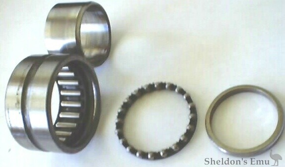
The roller bearing used in this conversion is an INA.NKIB 5906 C3 . It's a combination needle /roller, ball bearing with a two part inner race. Dimensions are 30 mm ID, 47 mm OD, and 23 mm Width. The C3 clearance allows more crush on the bearing, as its internal clearances are larger than STD. The case should be machined from the inside using the mating face and bush hole as reference points. The hole is bored 1.8475 to 1.8480 inches, giving 0.002 to 0.0025 inches interference. To fit the bearing, heat the case till it sizzles spit, then drop it in. It's important that you remove the plastic ball bearing cage first!
The depth of the hole is 20.5 mm measured from the machined area that the original bush sat against. The bearing rests against the step left in the hole. It is important that the bearing when fitted covers the 2 holes, 1 from the oil pump and the other to the oil pressure relief valve. A groove 4 mm square is machined around the bearing to join these two holes. If this groove coincides with the BEARING oil groove, oil pressure to the big ends will be LOST!!!


A hole is drilled from above the bearing inside the crankcase, to meet the bearing oil groove. A groove in the sidewall of the case forms a channel for the oil to run. I also drilled a hole in the top web and scalloped the area to act as a catchment for oil, much like the one for the idler gear. The area of the case that prevented the bush from turning must be machined flat all the way to the curved part of the crankcase.

If you don't like the idea of the bearing surviving on splash only, you can add this. There is an oil gallery that runs above the bearing and you can back drill a 1.5mm hole into it. That way when the oil pressure relief valve opens at 60 psi the first thing to get a squirt of oil under pressure will be your main bearing!

In this pic you can see the oil gallery position above oil pressure relief valve. I drilled out the oil gallery plug and replaced it so I could clean the passage after drilling.

This is the way the oil flows in this type of conversion. From the oil pump it splits in 2,part goes through the new oil gallery up the wasted oil pump-fixing bolt to a bridge that takes it to the crankshaft quill and on to the big ends. The rest goes around the new 4 mm square-bearing groove to the pressure relief valve and some is bled off to a 100 psi glycol filled oil pressure gauge.

This drawing gives a list of the parts required for the oil gallery conversion. A change to the A65 type of anti-syphon setup where the ball bears on the back of the oil pump is superior.

This drawing gives the dimensions of the oil gallery modifications that are required.

This picture shows the spigot and anti-syphon ball in position. Also the weld closing the new oil passage and direction it is drilled.

Oil pressure gauge take off hole.

This drawing gives the dimensions of the crankshaft end feed oil bridge.

This drawing is of the oil pump modifications.

Exploded view of oil pump and bridge.
1/ Wave washers ¼", 3 of.
2/ Fiber washers ¼", 2 of.
3/ oil pump gasket same thickness as D.
A/ Top hole for bolt F that passes through bridge G
B/ Bottom hole for bolt H.
C/ forward hole for bolt I that passes through bridge G
D/ Oil pump gasket, top hole larger to go over spigot, outlet hole enlarged to allow anti-syphon ball to bear on back of oil pump. Inlet hole enlarged to give better flow.
E/ See oil gallery parts drawing above.
F/ Top hole wasted bolt. Allen head cap screw head machined 45 deg. Under head 5 mm machined at 45deg. to 3 mm dia. Total length under head 68 mm last12 mm threaded.
G/ See crankshaft end feed bridge above.
H/ Allen head cap screw 45 mm under head.
I/ Allen head cap screw 55mm under head.

The crankshaft is machined to a diameter of 1.180 inches [the same size as the Drive side] all the way to the web leaving a small radius. The threaded part of the crank is machined to a length of 29 mm measured from the end of the crank to 1st step.A 3/16'' hole is SLOWLY drilled through the end of the crank till it breaks into the original oil gallery. Then a 1/4'' hole 9mm deep is drilled to accept the quill. The S/S quill is 20 mm in length with a 3/16'' hole through the center. There is a 8mm section with an OD of .002''larger than ¼'' which is pressed into the end of the crankshaft. The rest of the quill is 3/8'' OD un machined. The crank must be well supported when pressing the quill home. After the quill is pressed home it is machined to a final OD of 8 mm. From the end of the quill to the 1st step is 12 mm.

In the pictures below the split inner race can be seen on the crank. What are not so obvious are the shims [same type as drive side] behind the race, which positions the crankshaft central in relation to the bores. This must be done BEFORE the drive side bearing is shimmed to allow for crankshaft expansion. I give the drive side bearing .010'' clearance just to be on the safe side. It gets bloody hot here in OZ!


After shimming the crank you will have to make the spacer that goes behind the crankshaft timing gear, which locks every thing together. This is done by measuring the distance between the end of the inner race and the back of the crank gear after it has had the back ground flat.
A/ Spacer: OD = 40 mm ID = 30.25 mm Width = To be determined, see above.
B/ Crank gear 67-0339 Must be reduced in thickness to 15.5 mm. Material is to be ground off the backside of the gear.
C/ Washer Part# 67-0645
D/ O/P worm gear 67-0642 = 1mm must be ground off the hex end of this gear.
E/ Lock washer Part# 67-0644
F/ Left hand nut Part # 67-0643 Must be reduced in thickness to 3 mm.

Well that's it. I think I have covered everything and if I haven't I expect I will hear about it real soon! Ok I suppose now is the time to tell you there is a simpler conversion that does not require any alterations to the oil galleries except putting in the groove around the main bearing. If you drill a hole from the outlet of the oil pump into the top fixing hole then no modifications to the galleries is required as the oil is split off in the pump and feeds the crankshaft end feed bridge. An anti-wet sumping valve would be a good idea. I personally don't like this setup. But many people do and run this conversion successfully here in OZ. You can use the A65 part of the oil gallery conversion, were the anti-siphon ball bears on the back of the pump if you want.


Disclaimer: The information given here is for your interest only and is correct to the best of my knowledge at this time. Any modifications done using this information is done at your own risk no responsibility accepted!
RIDE SAFE