IN the future both the twin and single-cylinder Rudge machines will be available fitted with a four-speed gear box. Neatness and compactness of design characterise the new box. Double helical teeth are employed, all gears being constantly in mesh, and ball and roller bearings are fitted to all parts, with the exception of one end of the kick-starter shaft, which runs in a plain steel bush.
Eight pinions are used in the box. One is fixed on the driving sprocket sleeve, and it meshes with one fixed on the layshaft. On the other side of the main shaft is fixed a small pinion meshing with another running freely on the layshaft. Between these two pairs of wheels are two other pairs of pinions sliding on splines which are suitably removed from those parts of the shafts on which the wheels must run free in certain gear positions. Both sets of wheels slide in pairs.
Selective Action.
Top gear is obtained by bringing the left pair to the extreme left, and the main shaft wheel engages the dogs of the sprocket sleeve pinion, giving a solid drive. By sliding the pinions to the right the layshaft wheel engages splines on the layshaft, and the fixed wheel thereon drives the sprocket sleeve pinion through its fixed wheel ; this is the third speed.
When second speed is needed, the left pair of pinions return to their midway neutral position, and the second pair is brought to the extreme left, both pinions being on splines. Moved half-way to the right, the main shaft pinion comes on to a free portion of the spindle, and a pinion dogs engage those on the layshaft free pinion and the low gear drive is obtained from the main shaft fixed wheel to the layshaft fixed wheel and the sprocket sleeve.
The selectors are two segments in which are cut cam slots so arranged that one is in neutral while the other moves the gears, and vice versa. Each cam slot engages a pin and roller on the forks which move the striking plates inserted in the grooves between the teeth of the sliding pinions. By removing a cover plate the selector mechanism is readily accessible.
Carried in the hollow layshaft is the kick-starter shaft, which is well supported by roller bearings at one end and a plain steel bush at the other. All the kick-starter mechanism is enclosed.
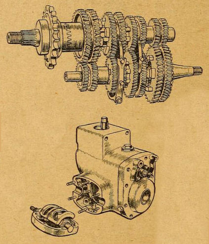
Main and layshafts of the Rudge four-speed gear ; the kick-starter mechanism and clutch are not shown. The use of double helical pinions is unusual in motor cycle practice; it should be conducive to extremely silent running.
On the Rudge four-speed gear box the selector mechanism may be removed with the inspection cover while the box is in position on the frame.
Control Mechanism.
Mounted on a bracket brazed to the front down tube of the frame is a gate change and lever, which is adjustable for position. Running from this bracket is a long connecting rod which operates a bell crank on a bracket mounted on the seat tube. This bell crank in turn actuates a link connected to a lever on the selector shaft.
Standard gear ratios employed on the single-cylinder machine are : 16.3 to 1, 11 to 1, 7.15 to 1, and 5 to 1. On the 998 c.c. twin the gear ratios are : 13 to 1, 8.8 to 1, 5.7 to 1, and 4 to 1.
The MotorCycle November 23rd, 1922.