![]()


This is my five year old daughter on the 1926 Model 44 racing outfit!(summer 2000)
Refurbishing
Apologies for the dropsheets, paint tins and scattered detrius. More information...
This page contains information about rebuilding your norton, and other interesting material.
The hints and tips have come from my own experiences, which have often been learnt the hard way! If you have any good ideas then please do not hesitate to send them to me and I will include them on the page ....we have the responsibility to keep these fine machines in good working order.
"It is true, that we cannot tell at once whether we have really gained any new knowledge by this or have only enriched our store of formulas......."
Sigmund Freud, 1923. The Ego and the Id. S.E. vol XIX p.152.
The most wonderful point about the Norton machine is its graceful, and almost fragile, appearance; it looks the beau ideal of elegance, in fact it suggests effeminacy; you find yourself wondering where its marvellous strength, and power comes from. it is so scientifically designed, that the art of its construction conceals its herculean capabilities, it must have taken years of study to perfect such a "multum in parvo" of power. It may be driven at a walking pace or at 50 miles per hour, or if a greater speed is desired an 8hp machine will carry you along at 80 miles per hour with perfect comfort if your respiratory organs will stand it.
From The Gentleman's Journal, 11.2.1911
PLEASE BE SPECIFIC ABOUT YOUR ENQUIRIES
Similar to a standard road going machine (the famous Model 18) it features many 'go-faster goodies' inside the engine.
Also has eight inch brakes front and rear, TT Amac carb, Lucas TT magneto, straight pull twist grip, TT gearbox...
1. NEVER blast clean an oil tank.
... and if possible do not blast clean anything. One stray bit of grit, stuck in a crevice with burnt old oil and shit for fifty years can at a later date cause havoc! Elbow grease works best!
2. If you blast clean crank cases, the ONLY way to make sure that all of the crap is clear of the internal oil ways is to use: extra long twist drill bits ( 3/16th & 7/32nd inch ) and to turn them by hand through the oil ways. High pressure air and cleaning fluid may not clear a partly occluded oil way; I learnt this the hard way!
3. Piston clearances: bottom skirt clearance 0.005 inch and up to 0.010 for racing machines
4. Oil leaks from SOHC engines. Make sure that the cam shaft tunnel is not broken, due to worn rocked pads allowing the bottom side of the rocker arm to hit the tunnel. I can repair this defect. See tip 21, below.
5. Sloshing Effect
Avoid drinking too many beers before riding your machine. The well known "sloshing effect" of a large quantity of fluid in the stomach can induce tank slappers. My friend, Roger, is currently experimenting by eating a meat pie with every pint of beer he drinks, prior to climbing onto the machine, to reduce the effects of sloshing. We are currently analysing lap times and further information on this topic will follow.....!
6. Dolls head and upright gear boxes are liable to break the top mounting "ears". This is usually due to a fault at the lower mounting. The lower mounting hole tends to "elongate" in a fore and aft directing as a consequence of the engine trying to pull it forward and the rear wheel attempting to pull it backwards. The bolt also wears. When this happens to a severe degree then the top mounts are put under strain and eventually break. The remedy is ensure a perfect fit of the lower mount. I bore out the "oval" holes and fit bushes which are lined reamed together so that there is a exact 1/2 inch hole (and perpendicular to the frame ). Sometimes "top hat" bushes are required to take up any slack in the transverse dimension. Make a new bottom bolt. The aim is to establish a snug fit of the lower mount.
Another way.... On some old and shagged out machines, both the ½ inch holes in the gearbox and also in the frame are no longer round. On a bike I was working on last week, these hole were worn and oval and consequently the gearbox could be 'twisted' or 'rocked' from side to side. My remedy was:
Firstly drill out the worn holes with a 13.5mm bit (13.5 mm = 0.531 inch) in both the frame and the lower mount of the g/box shell. You must do this accurately, so that the new holes are precisely perpendicular. A Bridgeport or similar size mill makes the job easy. I then skimmed each side of the lower mount of the g/box shell flat and square.
I then took a piece of 9/16th inch (0.562 inch) EN 1A bar and turned it down in the lathe to a diameter of 0.532 inch with either end turned further down to 0.500 inch. I screw cut 26 TPI threads to either end to take the appropriate cycle thread nuts. Then by using a reamer, I reamed all three holes (gearbox and both sides of the frame) out a tad, so that the new bolt was a snug tap fit. With the g/box shell held in place by the new lower mounting bolt, I could see that there was gap on either side to the frame. With the top mounting "ears" in the correct, central place; the gaps at the lower end of the g/box to the inside of the frame was 0.020 inch on one side and 0.032 inch on the other. Make up two appropriate size shims and 'BOBS YOUR UNCLE', a perfectly fitting gearbox.
7. OHV Valves and Guides
500 cc OHV NORTONS FROM ABOUT 1934 TO 1962 use roughly the same guides and valves. Depending on the source of information, Tranco or James catalogues, the dimensions are as follows:
Guides : total length 2 5/32 inches length to flange: 1 5/8 inches bore 3/8 inches O.D. 5/8 inches
Valves: head diameter 1 3/4 inches Stem diam 3/8 inches Stem length from 4 5/32 to 4 5/16 inches
Head style semi-tulip Stem head taper groove
Guides are cast iron. Remember to check the I.D. of the aperture in the head...you made need an over-size guide
1935 ES2 cylinder head with re-cut valve seats. Thin blue line depicts narrow seat on inlet: to allow maximum gas flow on immediate opening and perfect tick over. Thicker exhaust valve seat helps with dispersal of heat from 'red hot' valve. Easy job by using 'Neway' triple valve seat cutters. First cut is at 60 degrees, second at 31 and final cut (for seat) is at 46. Picture and diagrams demonstrate, click on thumb nails.
8. Gearbox Tip
Replace drive side lay-shaft bearing (40mm O.D. x 17mm x12mm) a no. 6203....by...a NJ203 roller
9. Petrol Tank Painting
In response to numerous enquiries regarding petrol tank painting; and to save me time on e-mail replies......here are my ideas. beware of the idea of "original". painting of tanks in the pre- and post war period was done by hand and on some days of the week, the hand responded to its brain in slightly different ways. ( I once met an old chap at the isle of man, who actually was a painter at Bracebridge street and he told me this! ) sales literature does not always follow the style that left the factory. some tanks were chrome plated, some were in dull nickel, some were never plated. panels were in silver with black and red lines. in the majority of tanks the red line was inside the black, but occasionally this was reversed!! I would never recommend re-chroming a petrol tank. the amount of pre-plate polishing required to provide a suitable service for chroming, leaves the metal dangerously thin in places and with disastrous consequences!!!!!!
I like the following, which although not original, looks better than the pictures depict! where the chrome should be is silver and where the silver is, is polychromatic grey !!!!!!!!!!!! ( both Norton colours ) click on thumbnails to see what I mean.....
INCIDENTALLY, THIS MACHINE IS NOT ORIGINAL EITHER.IT IS A SHORT STROKE ES2 MOTOR (now 84mm bore and 79mm stroke), downdraught inlet track, two spark plugs, and a lot of special bits inside! Incidentally, the paint was applied by JBS MOTORCYCLE PAINTING ( check them out on my links page )
10. Norton Silver can be replicated by using: 1974 VW Beetle silver, or Vauxhall star silver mist, or Vauxhall silver starfire metallic,or for a "greeny" patina, then use Vauxhall Platinum starfire metallic Rover silver leaf, MME421 is also a good match.
POLYCHROMATIC GREY: Fiat dark grey metallic; Ford Granada pearl grey metallic or VW Audi platinum ( ICI: L98G 9305B )
11. Seven pre-war inter tanks
Seven pre-war inter tanks are all different!!!! The one at the end is a new reproduction in aluminium.
12. Brake Drum Bearings
The 40mm X 17mm X 12mm bearing for the lay shaft is identical to all pre-war single sided brake-drum hub bearings, on the "spoke" side. On the "drum" side they were same OD and ID but wider at 16mm because it was a double row ball.
13. Tuning for Speed
Quite simply the best information on preparing old motorcycles is to be found in Phil Irving's "Tuning for Speed", which was taken from his slide rule articles.
14. CLUTCH INFORMATION
The AMC clutch was a re-design of the old Norton clutch. Dimensionally, it is the direct replacement and the two are interchangeable. But the internals are quite different. Whereas, the Norton has inserts in the chain-wheel and externally driven friction plates, the AMC is exactly opposite. The chain-wheel is solid and the friction plates driven internally. This was an improvement over its predecessor, especially in racing, where the old Norton clutch had some shortcomings. So although the two clutches are identical externally, and completely interchangeable, the components are not, with the exception of the pressure plate, which is pressed steel on the Norton, and alloy on the AMC. You can use the AMC pressure plate on a Norton clutch, the only advantage is that it won't rust when you run with open primary drive. The AMC was fitted to all the big AJS, Matchless and Nortons which used the AMC box from 1957 right up to the Commando. Either clutch will fit any Norton or AMC box from 1934 to 1978 including Commandos.
When setting up the clutch, it is extremely important to make sure all the plates are flat, any bent ones should go in the bin! Make sure the securing nut is tight; use a clutch holding tool. Make sure that all three springs are the same length and strength. When fully assembled, with primary chain on, and machine on stand ( ie rear wheel in the air ); put into first gear. Pull in clutch lever, and spin rear wheel. Note if the pressure plate is lifting evenly .....if not adjust the appropriate spring. Always allow free play on cable ( to avoid drag ), especially with races which have clutch starts. Good luck.
15. Primary Chain
NEVER run your primary chain too tight; 1 to 1 1/2 inches up and down movement.
16. Oil Tap
As a consequence of the effects of gravity, the contents of the oil tank finds its way past the gears of the oil pump to languish in the bottom of the crankcases. This phenomena is known as "wet-sumping". The time it takes to significantly wet-sump varies: a machine left for a few weeks may accumulate enough oil ( a pint or more ) to hinder the movement of the fly-wheels and therefore starting...
.... THE REMEDY: FIT AN OIL TAP AND REMEMBER TO TURN IT ON!!!
A ONE WAY VALVE IS A POOR OPTION BECAUSE YOU CAN NEVER BE CERTAIN THAT IT HAS NOT GOT STUCK CLOSED.
If you suffer with a poor memory, lack of concentration or are just plain stupid, then write in large letters on top of the tank the words "oil tap". Or you can fit a magneto cut out on the oil tap.
17. Sensible Questions
I frequently get asked for parts which I do not have. Gaskets, simple brackets, nuts and bolts, other fasteners etc are SO EASY to make. So make them yourself! I recently had some fool ask me: "What type of glue should be used to stick on tank rubbers"? For heaven's sake...... I am usually reasonably polite in my answers, but I get at least 10 e-mails a day so please make your question sensible.
18. Gearbox Data
Information about gear boxes, courtesy NOC.
19. Alloy Head Threads
All aluminium cylinder heads exhaust ports with internal threads, where the exhaust 'Nut' or 'Ring' screws in are liable to damage. Over the years, the combination of vibration, lack of maintenance and 'wear and tear' means that one day the set up gives up! Here are a few tips. It is best to undo the 'Exhaust Ring Nut' (ERN) when the cylinder head is hot or at least warm, so that the relative expansion of the alloy cylinder head allows some loosening. If you have a cold engine and the ERN appears tight then use a Hot Air Gun (a very useful tool to have in the workshop) to heat the adjacent area. If you are working on an engine which has stood for many years, the inevitable carbon deposits in the exhaust port will have found their way onto the threads of both male and female components. In combination with other dirt and muck, this acts as a 'grinding paste' and undoing a tight ERN under these conditions can cause a lot of damage.
If on inspection the internal thread is damaged and/or worn and consequently the ERN is either a sloppy or poor fit, then a repair is required.
I mount the head on an angle plate on the Mill and bore out all the old and damaged threads. I then measure the ID of the smooth bore left; add two thousands of an inch to this dimension. Now make up a sleeve which has its OD to the same numerical value; in other words it will be 0.002 inch larger than the hole! Internally screw cut a new thread which compliments your ERN, which will be in perfect condition; if not you must make or buy a new one. The length of the sleeve should be about 1/8th of an inch longer than the depth of your hole. When your new sleeve is finished, shove the cylinder head in the oven for ten minutes and then drop the sleeve in and finish off with three (120 degrees spacing) small welds to 'belt and brace' the job. The reason for making the sleeve 1/8th inch too long will become apparent when you do the welding!
Your ERN should be a perfect fit. When tightened up, finish the job with lock wire or other locking device and your pipes will never dangle!
 Click on
thumbnail
Click on
thumbnail
20. "FREDS"
| DIAM. | UNF | BSF | BSW | UNC | CYCLE
|
| 3/16 | 32 | 32 | 24 | 24 | 32 |
| 1/4 | 28 | 26 | 20 | 20 | 26 |
| 5/16 | 24 | 22 | 18 | 18 | 26 |
| 3/8 | 24 | 20 | 16 | 16 | 26 |
| 7/16 | 20 | 18 | 14 | 14 | 20/26 |
| 1/2 | 20 | 16 | 12 | 13 | 20/26 |
| 9/16 | 18 | 16 | 12 | 12 | 20/26 |
| 5/8 | 18 | 14 | 11 | 11 | 20/26 |
3/16 UNF~2BA (31.4 TPI) BA = 1/8, (38.5 TPI)
21. Inter Cam Box Repairs
The single knocker cam box, as used on all the 'cammy' models from 1931 to 1958, is a poor design, is prone to break, is difficult to work on and it leaks oil like a primary chain case! Why Norton persisted with it for over 25 years is anybody's guess? Most of the research and development was done on the double knockers, although in 1935 the works machines sported an enclosed cam box.
The most common fault with the cam box shell, is a broken tunnel. This is usually due to excessive wear at the rocker pad ends, which in turn means that the underside of the rocker hits the tunnel, causing the latter to break up (marked with a red line in the photograph). The purpose of the tunnel is to keep as much oil at the cam to rocker pad interface as possible and when it is broken, the oil loss from the cam box becomes so bad that most of the riders bottom half and the machines rear end are drenched in the stuff! The tunnel can also be damaged by inexperienced mechanics (bl**dy idiots) who do not know how to remove cams and replace pads.
The next most common fault with the shell is a broken 'leg' due to someone failing to check that all four mounting points for the cam box are perfectly horizontal and square (extended head bolts on the Models 30 and 40, individual spacers on CS1 and CJ).
As in all alloy (or magnesium) castings, threads are often damaged and mating surfaces scored by careless use of the wrong tool!
To repair the tunnel, I machine away the broken item so that I am left with a cam box minus its tunnel. I then make a new tunnel from a piece of alloy tube (2.125 inch o.d.) and use Araldite and a 2BA countersunk screw to fix it in place (see pictures). There is more than one way to machine the cambox; spin it and hold the tool or viscera-versa! Watch How I do it!
MVI_cambox.avi Video missing
When working on the cambox, I use a variety of special tools and jigs. The simplest 'holding jig', taken from Garratt, can be easily made from a six inch length of hexagonal bar and two 3/8 inch studs. It makes life very much easier. Being hexagonal, the jig can be turned round to work on both sides of the cambox, tilted at a convenient 30 degrees.
Once the cam box shell is perfect, then all the other components can be repaired and rebuilt. It can take a very long time to do all this work and it would take me even longer to write a manual on SOHC cam box re-building! My advice is to NOT do this work unless you have someone with previous experience to show you how. There are many potential traps!
Inlet Valve Opens 57/58 BTDC
Inlet Valve Closes 60 ABDC
Exh Valve Opens 85 BBDC
Exh Valve Closes 42/43 ATDC
This is for Mega or open pipe. With silencer retard inlet by 10 degrees, ie 47/70
These timing figures can only be achieved when there is no wear to the cams, or rocker pads. For timing the cams from scratch the following procedure should be adopted:
Exh No. 5 Inlet No. 1
Exh No. 6 Inlet No. 2
Exh No. 7 Inlet No. 3
10.Good luck!
Norton International cams
INLET EXHAUST MODEL
1932 E41.33 E41.34 40
1933 52.40 52.39 30
1937-39 63.92 63.93 C.S.1.
1937 68.93 E63.87 30
1939 39.40 39.39 40M
1948-52 & EARLIER? 62.12 62.13 30
1946-49 & EARLIER? 115.87 115.88 30M
1953-58 64.66 63.89 40M
77.63 40
1937 WORKS ENCLOSED C/BOX 4IN 4E 30M
These numbers probably mean something, but I have yet to break the code!
You would have thought that they may correspond to the cam timing, but they do not!
Anybody know the answer?
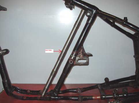
22. Rigid and Plunger (Garden Gate) Frame Breakages
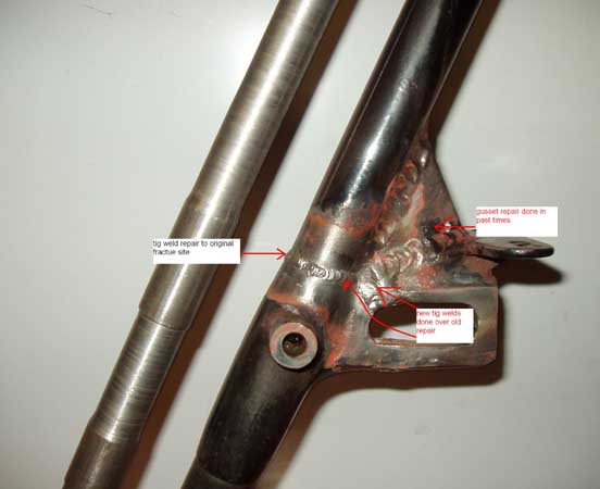
Norton first introduced rear suspension in 1936 for the works entered TT race machines. With heavy castings and un-damped 'suspension units' attached to the rear of a rigid frame, a few of the bumps on Monas Isle failed to make their way to the backsides of messers Guthrie, Frith and White. With the extra weight and decreased rear end rigidity, the already brittle frame which was prone to fracture on the saddle down tube, just above the gear-box top mounting cast lug, was put under further strain.
On both rigid and plunger frames I have frequently come across such breakages in both the workshop and on the road.
I have recently bought a 1939 Model 30M, which was raced by Victor Gaunt in the '46 and '47 MGP races. He had bought the machine in early 1939 to race in that years MGP, but 'The Hun', put a stop to all that. On stripping the machine I found that the frame had cracked just above the gear-box top mounting casting, it had been repaired in the past, but had cracked again.
Incidentally, this frame with the rear suspension units and "suicide" rear stand weighs in at a whopping 21.5kg (47 lbs). A rigid frame weighs about 15kg (33lbs).
It is important to carefully scrape away the paint from this area, even if a crack does not appear apparent. Beware of powder coated frames; I never use powder coating because its thickness masks the early signs of cracks.
Having cleaned up the offending area, I then considered the best way to effect a repair.... I sat down for a good pint of ale.
I put the tube in the lathe and skimmed down 35 thou, (reducing the wall thickness to 0.100 inch) Plenty strong enough! Where the tube is adjacent to a casting/tube joint, I left it full wall thickness; a nice snug fit in precisely the area you need the strength.
I then had another bottle of fine ale and considered the final touch. Having got everything as clean as possible (removing 70 years of road shit and castor oil mixed as sticky paste from the bottom of the saddle tube), I thought about the fixing of the tube? Was there a need for a couple of strategically placed pins (1/8th inch diameter, on a 1 degree taper, and tapped through a 1/8th diameter hole tube in both the new and old tube AND then silver soldered? Should I TIG or silver solder the top and bottom of the new tube inside the old saddle tube? How about a good dollop of 'J B WELD' in the significant places?
I finally decided that because my fortuitously found piece of tube was new (and hence easy to get scupulously clean) and with some careful cleaning of the inside of the original saddle tube; I brazed the new tube at the top and bottom. No need for any other fixing and hopefully the new tube will hold it all together.
All in place, drink lots more beer, assemble the machine back together and off for a good thrashing down the lanes!!
23. CYLINDER HEAD JOINT
An all the single cylinder engines I have worked on (from an all iron head & barrel twenties OHV to an all alloy sixties DOHC Manx) the same principals and engineering apply.
There is NEVER a gasket. The idea is known as the "double ground joint".
The theory is simple, the engineering a little more difficult.
The head joint comprises of two parts; the spigot interface and the wider head barrel joint. Say, the spigot on the barrel is 0.125 inch high, then the recess in the cylinder head needs to be 0.124 inch. This means that the seal is at the spigot joint and the wider joint is to prevent distortion.
The practically, especially on well used alloy top ends is a tad more difficult. If you measure the spigot height on the barrel, it is unlikely to be the same all 360 degrees around. The same applies to the wide surface on the barrel. With frequent and less frequent heating and cooling over 50 years the original manufacturing tolerances have been lost and distortion has taken place. On a fifties Manx engine I worked on last year the barrel, at the wide flat surface was distorted by 0.008 inch and at the spigot, 0.005 inch. The cylinder head was worse, with the wide surface being 0.013inch off flat!
Consequently these defects need to be corrected.
Mounting the barrel in the lathe and truing up and machining is relatively easy, but the cylinder head is more difficult. A special jig has to be made up to allow the truing up to be established. A good medium size lathe, grip true facility, magnetic face plate and some clever thinking is required.
The goal is to obtain a double joint with the spigot of the barrel mating in its recess . For Iron head and barrels, there is rarely any distortion and the easiest way to obtain a good joint is as follows: Hold the cylinder head upside down in the vice (securely but without causing any damage). Put some coarse grinding paste on the broad surface and fine in the spigot recess and add a few drops of thin oil to both. Carefully fit the barrel onto the head and with a anti-clockwise and then clockwise rotating motion, lap the two together. After a few minutes, wash of all the paste and oil and inspect. You should be able to see the lapping on all surfaces. Repeat until a perfect face on both broad surfaces and spigot are established.
Torque Iron set ups to 45 ft/lb and aluminium one to 32 ft/lb. You can use a very slight smear of either a hard setting goop or even a smear of oil or grease, which will burn hard.
Hey Presto, no more oil leaks.
Click on joint.jpg to see what I mean.
24. Valve timing on OHV and SV engines.
One of the most frequent e-mails questions I receive is about valve timing. For some it appears to be a black art or science beyond their intellectual capacity, but, in fact, it is not that difficult.
The opening of the inlet and the closing of the exhaust are the important figures to get correct.
An Instruction manual is also important, to give you the timing figures and usually a good description of the procedure required. I used to provide a photocopying service, but the hassle involved was not worth it. These days, ebay will always provide you with an original, a copy, or in CD format.
On the SV and OHV engines there are usually timing marks (or dots); one on each cam wheel and two on the half timing pinion.
Note the half-timing pinion is a LEFT-HAND thread.
If there are no marks, then you have to work it out. Click on valtiming.jpg to see a chart of timing figures.
25. Powder Coating.
The ONLY components I have powder coated are stands and seat frames. Powder coating is thick and very durable and is consequently excellent for these parts. For frames it is VERY BAD NEWS; because it has the above qualities it can hide the first signs of frame fractures, particularly at the common stress points where a tube enters a casting lug. So if you buy an old Norton with a powder coated frame, which may look quite good, but I doubt it, the FIRST job is to get it all off! Not an easy job, because it sticks like dog shit. A sharp knife and a blow touch will help. Powder coating cannot hide rust pitting; It amazes me when I see a so called 'restoration job' which features rust pitted mud guard stays, girder forks and other parts all powder coated and looking like they are made of.....rusty old metal; for goodness sake! Why do some people make such a mess?
26. Notes on Norton Numbering 'System'
The person who devised the 'system' of numbers (Model and date of manufacture) for Norton was either a fool or harbouring a strange sense of humour. There is no logic, there is an absence of mathematical principals and there is no system; it is akin to a random process.
At the start of his manufacture of motorised bicycles, 'Pa' Norton got it right. He called his first machine with an engine of his own manufacture, the 'Model 1', which later became known as the 'Big 4'. The Model 2 was similar to the 16H ('H' referring to home market) and the 17C ('C' referring to colonial market). The Model 3 was initially a belt drive Big 4 but later the '3' was used as the number for the 'Model 18', which was similar to the 'ES2' , which post war used the number 4 and no one even knows what 'ES2' stands for. In the twenties the Model 24 was similar to the Model 44, but different from the Model 34 and in the thirties the Model 30 was a 500 and the Model 40 was a 350!!
Before the Second World War, the numbers for frame and engine never matched and they did not follow a chronological order. For example frame number 50,000 maybe one year or more before or after 50,001! The engine numbers were almost in a sequence, but the 350's used a different system. This makes the 'looking up' in the Norton records a some what tedious process (unless a date of manufacture is given).
After the war, the numbers on the frame ALWAYS MATCHED and they followed a chronological order. For example 27,001 is the next machine off the production line after 27,000 . In 1946 Norton started the numbers again, from 1001! This means that engine number 80000 maybe from a 1937 Model 30 and also from a 1959 ES2; but post war Norton added a year letter. For 1946 this was 'A', 'B' for '47, 'C' for '48 and so on.
Engine numbers (and letters) are always stamped in ¼ inch and on the drive side crank case just below the cylinder barrel. Bore & Stroke dimensions are usually given (ie 79 X 100 is a 500; 71 X 88 a 350)
Frame numbers are always on the drive side of the frame and may be vertically or horizontally stamped, with a variation or two on both the position and the information! They are usually to be found on either of the two casting lugs on the front down tube; either on the tank mounting lug or the front engine mounting lug. On 'Featherbed frames they are horizontally stamped on the drive side gusset plate above the swinging arm pivot. The majority of Manx type featherbed frames also have the year and month of manufacture (ie 456 would be April 1956) stamped on the small bracket behind the top of the steering head tube (where the tank strap and cylinder head steady fixes).
The Norton records also have 'card numbers' for engine and frame which are usually stamped somewhere on the frame or engine, but this often confuses the picture and requires an extreme level of knowledge for the correct evaluation.
Click on norty-numbers.jpg to see a chart of all you need to know.
Fortunately the original factory records survive and are available to members of the Vintage Motorcycle Club (VMCC) to view at their most excellent library in Burton on Trent. They were previously held at the Science museum in Kensington, London.
These invaluable records are hand written in large (about A3 landscape) hard back books and amount to forty volumes in total; they are in reasonable condition and can be read quite easily. But in many cases the writer's pen was very poor in both quality and execution, which means it is sometimes difficult to read exactly what has been recorded. This applies particularly to the names of the dealerships the machines were supplied to and the subsequent names and addresses of the lucky new owners. Furthermore the use of abbreviations is inconsistent both in application and designation.
On all Post War machines, the frame and engine numbers match and they are despatched from the factory in chronological order. This means that machine D11M 20681( D for 1949, 11M for 500 Manx) left after 20680 and before 20682. This means that looking up a machine in the factory records is easy.
On all Pre War machines, the frame and engine numbers do not match. Neither are in chronological order. For instance, frame numbers 82384 and 83159 left the factory on the same day, although there engine numbers are separated by just one numeral, but in the reverse order. Furthermore, two adjacent numbers could be on separate reels and separated by a few thousand machines! This means that looking up a machine in the records can take a very long time.
I have a copy of the factory records on 16 reels of micro-film, which are very well reproduced on some reels, but on others the reproduction is totally un-readable.
This all means that if I am asked to check out a pre-war machine it could be easy (like 20 minutes scrutiny) or it might take all day and night! And this means that I only do it for those kind people to whom I owe a favour.
27. Girder Forks.
Most have had a very hard life and consequently will need repair work. Beware of girders which have severe rust pitting, they will not be strong enough for use. Replacing the tubes is very difficult because the availability of tapered tube is non-existent (unless anybody knows different). Check for straightness, by using long mandrels in the spindles holes and fork spindle location. fork check.jpg image missing
I make new spindles from EN16. For ½ inch spindles I bore out the worn holes in the forks to 9/16th inch, 1 inch deep and then fit phosphor-bronze bushes, 1 inch long. 9/16th + 0.004 O.D. and ½ inch I.D. I then ream the pair out with an extra long ½ inch reamer......perfecto! Final assembly. A jig to hold the fork makes assembly much easier; click on forkjig.jpg (also missing)
28. Gaskets
It is amazing how many emails I get along the lines of: "where can I
get a gasket set for my 1935 Norton
29. Ladies Hairspray.
Fitting rubber handle bar grips to bars and
throttles can be tough, unless you are built like Geoff Capes. Use ladies hairspray. Just spray some
in the inside of the rubber grip and push on. Hey presto easy! The hairspray acts initially as a
lubricant and the next morning it has reacted like a glue. It really works; no kidding.
Remember to put it back on the missus dressing table! 30. Check this out..... it is very funny.
31. Wheel building and offsets.
The only way to ensure that this is correct, is to
have your wheel building guy to make the measurements on your machine with either the old wheel in
position or the newly restored hub in its correct position. At the front this is central in the
forks and at the rear, it is with the sprockets lined up. I replace the various rear spindle
spacers with ones made from a good quality aluminium. Saves weight and looks good. You can also
replace the inside bearing spacer with one made from aluminium. Francis Beart always did
this and made numerous other components out of ally.
32. Norton OHC Manual
"Notes on the assembly of Norton cammy engines" is online here, courtesy vintagenorton.com.
I have been writing a comprehensive manual about rebuilding cammy engines for the past ten years. I hope to get it finished by
the end of 2012. It will be available on CD and will include a lot of data, pictures and important
information. Here is the first page:
SOHC (single over-head cam) engines
The first OHC engine, designed by Walter Moore, appeared in 1927 and brought immediate success with a win in the Senior TT that year for Alec Bennett and fastest lap with Stanley Woods. This engine did not fulfil the initial expectations and Norton was well and truly beaten on the race tracks of Europe from 1928 to 1930, predominantly by Sunbeam and Rudge. Moore left to go to NSU in Germany.
Arthur Carroll, the new Chief draftsman at Norton and Joe Craig designed and developed this motor. From 1931 to 1939 Norton racing motorcycles dominated and won practically all the Isle of Man races and European Grand Prix events. Only the odd Velocette and Italian or German machine would give them a run for their money. The privateer would also enjoy numerous successes in 'Clubmen events' and the lucky chap who used a 'Cammy' Norton on the road would always show his mates the way home.
Later Edgar Franks, Leo Kusmicki and Doug Hele continually developed the Cammy motors and there are a surprising number of variations, so to the builder, BEWARE!
The following notes are documented to help others who have not yet learnt about rebuilding, repairing, and tuning of these engines. I do not confess to know everything and I continue to learn from the mistakes that I make. The concept of a written manual is, perhaps a little old fashioned and consequently it might be better to produce a DVD of an engine rebuild. I tried this, but after hours, days and weeks of working out what all the little knobs and switches on the camcorder did, and many hours of filming an engine rebuild, I was unable to download the footage from the bloody camera to the computer! Far more difficult than a Cammy Norton engine rebuild! So if anyone wants to be camera man, director and producer for a DVD on this subject then please get in touch. I hope this 'manual' is easier to follow than the one Sony produced!
There are some basic principles that also apply to all of these engines. With the overhead camshafts being driven by a vertical shaft and two pairs of bevel gears it is absolutely essential to recognise the importance of parallel lines, perpendiculars and accuracy at all stages of an engine rebuild. It is equally important to acknowledge that we are playing with objects that are 50 to 75 years old and any student of metallurgy will tell you that all these parts are well past there useful life. Magnesium cases that have been exposed to hot temperatures while in a racing battle are very much colder when the treasured Manx Motorcycle is laid up in a cowshed in Scotland during the winter months. Hot means expansion and cold means contraction, which means main bearing housings, for instance, will tend to crack when in a frozen shed and then let go when hammering down the Sulby straight! Without sounding too pessimistic, the effects of dampness and consequential oxidation of surfaces also leads to impending mechanical disaster.
Unless you are very lucky, most of these engines have had a hard life and many are near to being totally 'shagged out'! They have been broken in the past and repaired by 'bodgers' with many replacement parts either fitted incorrectly or poorly engineered. Although the basic layout of the motors in the production run from 1931 to 1957 is the same, there are many small variations and consequently knowledge of these changes is important. For example the cambox and cylinder on the early models was held by 4 studs at a square distance of 2 1/8th inch, and from 1931 this distance was increased to 2 ¼ inch.
This engine was made in numerous variations:
Model 30. 490 cc: 79 X 100 mm to 'International' specification
Model 40. 348 cc: 71 X 88 mm to 'International' specification
Model 30M. 490 cc: 79 X 100 mm to 'Manx' specification
Model 40M. 348cc: 71 X 88 mm to 'Manx' specification
Model CS1. 490 cc: 79 X 100 mm
Model CJ. 348 cc: 71 X 88 mm
Model 596-: 596 cc: 82 X 113 mm; in International, Manx, CS1 and Trials variations.
The Carroll/Craig motor was first seen at the Olympia Show in November 1929 and was a hybrid of the Moore and Carroll engines which basically had the former designer's top end and the later bottom end; the exhaust pipe exited to the left (drive- side). Very few were made. The cam box was redesigned and this engine made its debut at the North West 200 in April 1930 in sensational style when Tim Hunt won the junior race on the 350 version. The 500 race saw Stanley Woods come home third. These early motors........... to be finished
We will start with the workshop. Besides having a decent set of spanners, a strong vice, a big hammer, an impact wrench (preferably air power to about 150 ft.lb. but ONLY used for undoing nuts) and a few pullers; you really need a lathe, a milling machine, cylindrical and surface grinding, all types of welding equipment, a spark eroder , surface hardening equipment, and about 50 special tools, jigs and fixtures to do the job properly! Most of us do not have this equipment and have to use other workshops to help out, but I would suggest that you have access to a lathe, because there are numerous times when bolts, studs, spacers and other fittings need to be modified for proper fitting or made from scratch. You must have a good set of Whitworth spanners (ring, open ended and sockets) and be prepared to make a few special tools and jigs.
33. to 1000.....
still in my head and waiting to be put into the written word.
1001. THE MOST COMMON enquiry that I receive is about whether or not a machine is in "original" condition or specification. The answer is: "NO and do not worry about it!!" Allow me to explain. In the days when you could order a NEW Norton from Bracebridge Street (and especially in the 20's and 30's period), a prospective purchaser could order "plate and polish" which was extra chrome et al, a sprint size petrol tank, or a large capacity IOM tank, different wheel sizes, in trials trim, with or without lights, folding kick-start, etc etc etc. Racing machines were frequently broken and re-built with the latest components (which probably were a year or two later than the original machine). Owners changed handlebars, paint schemes, and made sensible (and occasionally ridiculous) modifications...So how do we know what is "original"??? My 1920 Brooklands Racer has a circa 1940 carburretor on it, which seems to offend some people. My reply is: "If you can tell me where I can get the "original" one from then I will put it on the machine, provided it performs as well as the NOS 1940 item! The important point is to assemble the pile of bits into a working machine and then worry about trying to trace the "right" style handlebar rubber at a later date!!!
I modified a 16H frame to 500T specification, used genuine 500t petrol tank, oil tank, forks, yokes, front wheel and squeezed in a circa 1938 CJ motor....much more interesting to do this than try to return to original condition....so many of you guys out there are harbouring potential nervous breakdowns in your quest to obtain all the original bits; use 'em, break 'em, mend them and above all enjoy.
This picture has a story. While attending the Vintage Sports Car Club meeting at Wiscombe Park, Devon a few summers ago I was approached to take this very dear lady for a ride. Her name is the Honorable Bardi Frankland and she is 91 (ninety one) years old. She chose my mount, in preference to the two Bugattis, the ERA and the Alfa Romeo for a spin up the hill-climb! You certainly meet the most remarkable people while riding pioneer machines.