Page 109
CHAPTER VII
OVERHAULING
IF a machine is to be kept in efficient condition and its depreciation and repair bill reduced to the absolute minimum, it is essential that the rider should devote some considerable time to its periodic overhaul. Overhauls are of two types (1 ) the complete overhaul. (2) the ordinary overhaul. A complete overhaul is usually undertaken once every 8,000 miles, or about once a year. This overhaul should be treated seriously, and the whole machine should be dismantled completely. Every component should be cleaned, scrutinized, and, if necessary, replaced. The engine and gear-box must, of course, be removed from the frame for this operation. Special points to be noted in the complete overhaul are set out herewith.
frame. Alinement, existence of flaws or cracks, play in spring forks, looseness of steering head, wear caused by friction of all attached parts, condition of enamel.
WHEELS. Condition of taper roller bearings, truth of wheels, alinement, loose spokes, condition of rims, wear of tyres.
chains. Excessive wear, cracked or broken rollers, joints.
ENGINE. Oil leaks, compression leaks, main bearings, valves, valve guides and tappets, overhead valve rockers, valve springs, valve seats and faces, cotters, condition of cylinder bore, piston, piston rings, play in big-end and small-end bearings, timing wheels, shafts and bearings, cams, cleanliness of oilways.
GEARS. Condition of teeth on sprockets and pinions, damaged ball races, and loose parts generally. Do not forget index mechanism.
The examination should also include all control rods and cables, tank filters, clutch and brake linings, etc. To sum up. everything should be dismantled, cleaned, and readjusted.
An ordinary overhaul should be undertaken every 1500-2,000 miles. This should comprise decarbonization of the engine, valve clearance adjustment, adjustments of contact-breaker and plug points, valve grinding, general lubrication, and sundry adjustments.
Apart from these overhauls the rider should make a point of regularly going over the various nuts with a spanner. Vibration frequently loosens them. All working parts must also be kept well lubricated (see lubrication chart, Fig. 44), and odd adjustments made as they are needed. The rider who callously runs a machine until 'something happens' is asking for trouble and, moreover, will assuredly get it!
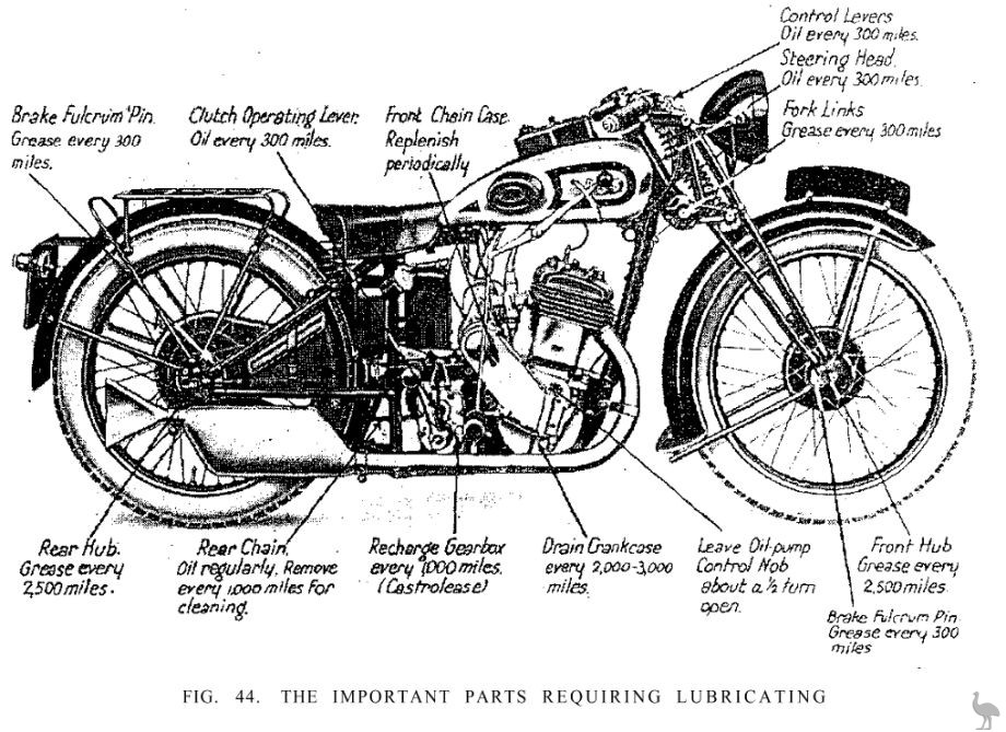
FIG. 44. THE IMPORTANT PARTS REQUIRING LUBRICATING
The above chart, depicting a T9 A.J.S., is intended as a general guide and need not be strictly adhered to. The chart is applicable to all of the 1932-33 models. In the case of the overhead-valve models there are additional points, such as the O.H.V. actuating gear requiring lubrication (see page 121). On dry sump models the oil tank should be drained every 5000 miles and the fabric filter (Fig. 18A) should be cleaned every 500 miles. On all models keep the oil tank properly replenished. On sidecar outfits there are also the spring pivot joints requiring lubricating
If a machine is properly overhauled and cleaned the owner will be amply rewarded for his pains by the machine giving long service, perfect running at small cost. Overhauling is by no means as tedious a business as appears on paper ; experience and common sense soon enable all overhauling to be done rapidly and easily, as it is required. For the guidance of those who are not yet proficient in the art of overhaul, or those who wish to have a work of reference, we will conclude this chapter by giving detailed instructions appertaining to all types of overhaul of A.J.S. motor-cycles.
Cleaning. Cleaning the machine is highly important; it is a necessary preliminary to overhaul. If neglected it renders overhaul difficult and results also in great deterioration of the plating and enamel, and the machine soon becomes shabby, and its market value rapidly falls. After a dirty ride in wet weather cleaning may occupy at least an hour. It entails the use of stiff bristle brushes and paraffin for removing the filth from the lower part of the machine, together with cloths, leather, and polishes for the bright upper surfaces. On no account should the machine be left soaking wet overnight. A serious amount of rusting may occur. If the rider has not the time available for systematic cleaning, the machine should be thoroughly greased all over before use.
Valve Clearances. In order that the valves shall seat properly at all engine temperatures it is necessary that clearances should exist between the valve stems and the rocker studs or tappet heads, as the case may be, when the engine is hot. The clearance should be checked now and again with the feeler gauge on the magneto spanner, although it is unlikely that adjustment will be required unless the valves have been ground-in or the engine partly dismantled. In the case of a new engine, however, the clearances will increase until the engine has been thoroughly run-in. Fig. 45 illustrates the point where the clearance should exist (C) and the means of adjustment (A) in both S.V. and O.H.V, type engines. This clearance should be 006 in. and -008 in. in the case of the inlet and exhaust valves respectively with a hot engine. In the case of the O.H.C. engines the clearances should be with a cold engine 016 in. and 018 in. The clearance of the exhaust valve is slightly the greater because this valve is subjected to greater heat, and accordingly the stem expands somewhat more than that of the inlet valve. To check and adjust clearances proceed as follows'
Turn the engine over until compression is felt; then raise the exhaust lifter and turn over a trifle more until the piston is at the top of its stroke. Before checking the clearance make quite sure that the exhaust valve lifter is not determining in any way the position of the exhaust valve tappet head or rocker stud. There should be a small interval between the time when the lifter is raised and the tappet head or the O.H.V, rocker commences to move. If this is not so the tappet foot or the toggle will not be resting on its cam. If the valve clearances are not correct this must be rectified. In the case of the S.V. engine, hold the tappet head with a spanner and loosen the lock-nut (B) below with another spanner: now screw up or unscrew the tappet head until the correct clearance is obtained, and retighten the lock-nut.
Check again after tightening the nut. In the case of the O.H.V, and O.H.C. engines, loosen the lock-nut (B) which is provided for securing the adjustable grub screw (A), adjust the latter, check the clearance at (C), and retighten. Check again afterwards. It is worth while adjusting the valve clearances carefully, for excessive clearance will produce noise accompanied by considerable loss of power, while insufficient clearance may cause actual damage to the valves, especially the exhaust valve, as well as loss of power. In the case of the O.H.C. engines valve clearances are comparatively large due to the fact that as the engines warm up the clearances decrease instead of increase, as they do with the S.V. and O.H.V, power units. An approximate setting can be obtained by screwing the rocker stud up with valves closed until contact is felt, slackening off half a turn and locking in position. It is, of course, much better to obtain the exact setting with a gauge.
Decarbonizing the Engine. After about 2,000 miles on the road the exhaust note becomes 'woolly,' instead of being a crisp 'bark,' and the engine sluggish and very prone to 'knock.' These symptoms clearly indicate that the time has arrived when the engine must be decarbonized, that is to say, all carbon deposits on the piston head and in the combustion chamber must be removed. Carbon deposits, incidentally, are due to three things: (1) incomplete combustion of fuel, (2) carbonization of road dust entering the cylinder, (3) burnt lubricating oil. When decarbonizing it always pays to inspect the valve faces and seats, and grind in the valves if necessary. In any case, removal of the valves enables the combustion chamber and also the ports to be very thoroughly cleaned. Before decarbonizing, it is first necessary to remove the cylinder or cylinders, as the case may be ; but whether the engine is a single S.V., a twin S.V., or an O.H.V, or O.H.C. model, the procedure is much the same. Overhead valve mechanism is apt to frighten some people, but actually there is nothing in it at all. All A.J.S. engines, except the 3-49 h.p. lightweight Model T5, have detachable cylinder heads. This greatly facilitates cylinder removal; there is no expert juggling required to get it off. Furthermore, the valves may be attended to, if desired without disturbing the cylinder at all.
Initial Preparations. In the case of Model T5 the cylinder barrel and head are in one piece and the latter cannot therefore be detached as on other models. Preparatory to removing the cylinder barrel on this machine it is necessary to detach the H.T. lead to the sparking plug, and disconnect the exhaust pipe and the steady between the cylinder and front down tube. Remove the steady
This engine, which is made in two sizes, 350 c.c. and 500 c.c, has double-row roller bearing for the big end, ball bearings for the crankshaft and the camshaft, channel section rockers, drilled sprockets for the rear magneto and camshaft drives, and an automatic spring tensioning device for the camshaft driving chain bolt. The Amal carburettor may either be left in place on the cylinder by removing the slides and the petrol pipe from the base of the float chamber, or, alternatively, the carburettor may be taken off by undoing the screw-in fastening.
When dealing with Model T9 with detachable aluminium alloy head the only preliminary operation necessary before removing the head is to disconnect the H.T. lead. In the case of the twin cylinder engine disconnect the H.T. leads and remove the plugs. If the reader's mount is of the O.H.V, type (T6, T8, TB6, TB8), first disconnect all fitments, such as exhaust pipes, carburettor slides, and then proceed to remove the tubes enclosing the push rods and the push rods themselves.
Push Rod Removal. To remove the push rods the special extractor tool (obtainable for Is.) must be used after shortening the two covers by undoing the lock-nuts and telescoping them. The end of the tool is arranged to fit over the rocker adjusting screw (Fig. 45A) in such a way that by pressing the tool handle down it compresses the valve spring. Press down on this tool and seize the base of the tappet tube with the other hand. The push rods may then be withdrawn by lifting their hollow cups off the tappets complete with covers. The rocker-box should now be removed.
Rocker-box Removal. To remove the rocker-box for the purpose of giving access to cylinder removal, the lock-nuts at the top and bottom of the push rod covers will, of course, have to be dealt with as first described. Next unscrew the four pins holding down the rocker-box. The two pins at the right or push rod side of the rocker-box need only be unscrewed until they are free, but those nearest to the valves must be withdrawn entirely. The rocker- box can now be drawn off the cylinder head from the right side.
Removing Cam-box on 1930 O.H.C. Engine. With this O.H.C. engine remove the cam box in a similar manner after taking off the cap and split fixing nut on the camshaft. While removing the cam box an assistant should hold and steady the chain-wheel.
Removing Cylinder Head. Next remove the bolts holding down the cylinder head, and remove the latter. Care should be taken to relieve the pressure evenly on both sides while untensioning the bolts. The head can then be removed by inserting a screwdriver, or similar tool, between the top cylinder-fin and head, prising upwards the head carefully off the barrel on both sides. Avoid scratching the cylinder head or the C. and A. gasket.
Drawing Off Cylinder Barrel. When the head is removed it is a simple matter to draw off the cylinder barrel. When doing this the engine should be turned over until the piston is at the lowest position of its stroke, and the barrel gently slid off, care being required to prevent the loose piston falling sharply against the connecting-rod which might damage or distort the piston skirt.
While turning a 'camshaft' engine support the chain wheel with the fingers, or a suitable instrument, permitting of its unobstructed rotation. On no account allow the chain wheel to fall out of the chain. Use the special supporting tool. Having removed the cylinder, wrap a clean rag round underneath the piston, so as not. to allow dirt or foreign matter to enter the crankcase. Remember, that should you by some mischance allow even the smallest article to fall into the crankcase {which the author confesses to having done once) it may be necessary to take the engine right out of the frame in order to extract the offending article?. Anyway, fishing for a small nut with a piece of wire is at the best of times depressing, especially on a fine afternoon! Before actually starting to remove any carbon the piston should be taken off. It is desirable to mark the interior of the piston to ensure its correct replacement.
Piston Removal. Decarbonizing can be carried out without removing the piston, but each alternate occasion it is advisable to remove the piston so that the ring grooves can be cleaned. On all A.J.S. engines the gudgeon-pin is of the 'floating' type, and is secured in position by two small retaining springs, one on each side. These springs fit into recessed rings in the piston bosses, and to be withdrawn must be squeezed together with the special pliers provided. Afterwards the gudgeon-pin may be pushed out from the driving or timing side. The piston can then be removed from the connecting-rod.
Removing the Valves. Valves of the side-by-side type can be removed, if desired, without disturbing the cylinder. Take off the valve chest cover and the valve caps in the case of a T5 engine, or remove the cylinder head in the case of a T9 engine and place the hooked end of the special valve extractor on the top of the valve, using the valve cap spanner, which fits the bottom of the hook, for the necessary leverage to lift the valve spring to allow the cotter to be withdrawn. The valve can then be pushed up and drawn out of the head. Remove the other valve similarly. Remember that side valves are more readily removed with the cylinder in situ. On a 33/2 or T9 use a proprietary extractor.
In the case of the engine with overhead valves it is necessary to remove the cylinder head entirely from the engine to enable the special valve extractor (price 5s. 9d.) to be used. This is a clamp-like tool for extracting the valves readily. For portability the tool is made to fold up. Unfold it and place the end opposite the screw over the upper valve spring cap in the manner illustrated on the next page. Screw up until the point of the screw presses inside the hollow of the valve head. Hold the cylinder head firmly, keep screwing, and it will be found that the spring is compressed. Then the two small split cones can be taken away from the recess in the valve stem, and the valve may be withdrawn. Repeat this operation for each valve. When removing valves, note where they come from and replace them in the same order. The valves are interchangeable on some engines, but it is best not to change them about unless necessary, as different steel is used.
Removing the Carbon. Procure an old screw-driver, or similar tool, and scrape off all carbon from the piston head. If this is done with the piston not removed be careful not to impose side strain on the connecting-rod. The piston may then be polished with very fine emery cloth, but do not touch the sides of the piston at all. With aluminium pistons the use of emery cloth is not advised, and if used great care must be taken to remove abrasive particles. If the deposit is very hard it may be necessary to allow the piston to soak in paraffin in order to soften the carbon. Now scrape off all deposits in the cylinder head, being careful not to scratch deeply the walls of the combustion chamber during this operation. Incidentally, it should be mentioned that carbon deposits form less rapidly on smooth surfaces, and therefore it is worth doing the job thoroughly. On no account use emery cloth or, indeed, any abrasive on either the combustion chamber or cylinder walls. Any abrasive particles left would cause very serious damage in the event of their finding their way between the
The engine parts shown are not those of a 1932-33 power unit, but nevertheless almost identical. The cylinder head stay shown at D is, however, now omitted
A - Cylinder barrel B = Cylinder head gasket C = Cylinder head D = Cylinder steady bolt E = Cylinder head studs
F = Rocker box complete with rockers G = Rocker box cover and screws
H = Rocker box bolts
J = Piston
K = Gudgeon pin and circlips
L = Valves (tulip)
M = Valve guides
N = Valve springs O = Split cones P = Valve spring caps R = Push rods S = Push rod covers
piston and cylinder. Chip off all deposits around the valve pockets and the ports, afterwards wiping all surfaces over with a clean rag slightly damped with paraffin.
Grinding-in the Valves. Should the valves or valve seats show signs of 'pitting,' the valves will have to be ground-in. This requires considerable patience and care. We will deal first with the S.V. type of engine.

On S.V. engines with detachable heads not housing the valves (33/2, T9) grinding-in does not necessitate cylinder removal, but care should be taken to screw down the tappet heads a few turns to ensure the valves seating with piston on T.D.C.
Stuff a rag into the combustion chamber or cylinder to prevent dirt getting in, and then, if removed, place the head or barrel firmly on a bench with valve seats uppermost. The best preparation for valve-grinding is a compound such as carborundum (supplied in two grades, coarse and fine).
Smear the valve face lightly with some of the coarse carborundum paste, and insert the valve on its seat. Only use a little of the compound at a time. Now oscillate the valve repeatedly under moderate pressure with the aid of a screw-driver or a screwdriver blade gripped in a brace. Lift the valve at intervals, and turn it round a few degrees before dropping it again. Remove it at intervals, wipe and inspect the face. If there are still signs of 'pitting,' apply more pastes and carry on. When there is a bright ring contact all the way round, and the little brown or black pock-marks have disappeared, the valve is a good fit again, and may be refitted. It is a refinement to finish off with a line grade of abrasive, or even with rouge or metal polish. After grinding-in both valves, carefully remove every particle of abrasive from the cylinder head. Never attempt to grind-in a. very badly pitted valve; it should be returned to the makers to be refaced. To grind-in such a valve effectively would cause very bad wearing down of the valve seat, and would ultimately result in the valve becoming 'pocketed,' with consequent loss of power. A light spring under the valve will assist grinding-in.
Grinding-in overhead type valves is very similar to the procedure described above ; but, of course, the valves, instead of being pressed down upon their seats, have to be pulled up against them. For this purpose a special tool is provided (see Fig. 50).
Having ground-in the valves and thoroughly cleaned out all dirt and abrasive, as well as any fluff on the valve seats, proceed to replace the valves and valve springs, together with the valve caps in the case of the 3-49 h.p. lightweight Model T5. When replacing valve caps, smear a jointing medium, such as 'Metalestine,' on the threads, also see that all copper-asbestos washers are in sound condition. Valves should be replaced in their correct places. The colour of the steel usually indicates which is the exhaust valve. As a rule this valve is rather blue. If it is greatly discoloured it is a sign of overheating having occurred.
Examining and Removing Piston Rings. The piston rings are the main guard of the compression. They must, therefore, be full of spring, free in their grooves, and set with their slots equally spaced round the piston, i.e. at distances of 120°. If all the rings are bright all the way round they are obviously being polished against the cylinder walls, and are perfect, and should be left alone. If, on the other hand, they are dull or stained at some points, they are not in proper contact with the walls of the cylinder. Perhaps they are stuck in their grooves with burnt oil, and will function properly if the grooves are cleaned. If vertically loose in their grooves or very badly marked, the rings must be renewed. Piston rings are of cast-iron, and being of very small section must be handled very, very carefully. If not, they will certainly be broken. They cannot safely be opened out wider than will allow them to slip over the crown of the piston. Therefore, to put them on or remove them requires the insertion of small strips of metal, about 'A in. wide, which are placed in the manner illustrated by Fig. 51. When fitting new piston rings, thoroughly clean the grooves into which they fit, as any deposit left at the back of new rings forces them out, and makes them too tight a fit. Paraffin usually loosens stuck piston rings. Piston rings are made to very accurate dimensions, and it is very bad practice to attempt to 'fit' oversize or undersize rings unless you know exactly what you are doing. Lapping- in oversize piston rings is a skilful job, and unless the slot sizes are exactly right the rings will not function well, and may even produce an engine 'seizure.' Therefore, always use piston rings guaranteed to be of A.J.S. manufacture. These have a slot gap of 00512.

The above is the accepted method, unless one has a special tool available
Lubricating O.H.V. Rockers. The rocker gear can be inspected by removing the inspection cover, but this need not be taken off in order to lubricate the upper ball joints of the push rods. In the centre of the cover will be found a 'Tecalemit' grease gun nipple (see Fig. 10). Grease should, with both valves closed, be forced through this nipple, when it will automatically find its way to the two ball joints. It is important when this is being done that both valves are in a closed position. If the inspection cover is removed, care should be taken to see that the two coil springs, which fit inside the rocker spindles, are not lost. These coil springs press against the inside of the cover, and have their other bearing against the end of the hollow rocker spindle.
Cleaning the Outside of Cylinder. Rain and heat soon make the outside of an air-cooled cylinder look red and rusty. This does not affect the running, but does not improve the appearance of the machine, and to a very small extent reduces heat radiation. To remedy this the cylinder head and the cylinder radiating fins should be cleaned with a stiff brush soaked in paraffin, and afterwards painted with cylinder black. There are plenty of such compounds on the market.
The Sparking Plug. Thoroughly clean the sparking plug with petrol and scrape the electrode points lightly with a sharp pocket- knife, afterwards checking the gap between them, which should be about 02 in. The reach of the sparking plug is also of importance. The sparking plug should be frequently inspected. It is susceptible to oiling-up.
Reassembly of Engine. After thorough decarbonizing, the engine may be reassembled. Care should be taken to replace all paper washers and C. and A. washers if fitted; any damaged washers should be at once renewed when reassembling the engine. The piston should be oiled before being attached to the connecting rod with the gudgeon pin. It must be replaced the same way round as taken off with the rings properly spaced. Do not forget the retaining springs. These must be a snug fit. Hold the cylinder in the rear angle of the frame, and place the piston a little before bottom dead centre on the downward stroke. By pressing the rings in with the fingers without disturbing the slot positions, the barrel may be slid over the piston. When replacing the cylinder of Model T5 remember that it must be tightened down before the steady is again attached to the down tube. When the cylinder has been finally tightened down, then the stay of the steady can be adjusted so that the pin passes through the clip on the down tube and eye of the stay without force. The rest of the assembly is quite straightforward. There are two points to be noted, however :
(1) see that the overhead valve rocker bearings are lubricated,
(2) make certain that the lift of the exhaust valve on the O.H.V, engine does not exceed V16 in. when the exhaust lifter is raised. If the valve lifter lifts the valve, say, V8 in., the inlet and exhaust valves may foul each other with disastrous consequences when the engine is restarted (this applies only to 1927-29 engines).
In the case of a camshaft engine, after replacing the cylinder and cylinder head fit the cam box, carefully placing the chain wheel on to the camshaft spigot and rotate the engine until the hole in the camshaft sleeve is opposite to the hole in the chain wheel. Now insert the washer with its special key and tighten the nut and fit the split cotter. Finally, remove the tool supporting the chain wheel and replace the inspection cap in the chain case. The remainder of the assembly is straightforward.
After assembly, test the engine compression by trying to pull the rear wheel over with top gear engaged. Do not stand on the kickstarter, as this puts an ill-advised strain on the gear-box layshaft bearings. It should offer powerful resistance for several seconds on full compression. But bear in mind that the compression will improve still further when the oil has circulated again throughout the engine, and the valves and piston rings have rebedded themselves again. The machine is now ready for the road again.
Carburettor Fitting. All 1932-33 machines except T5, 33/2, have flanged fitting carburettors, and it the carburettor is removed great care must be taken to ensure on refitting an absolutely airtight joint. If the washer is damaged fit a new one at once or the bad joint will result in air leaks and erratic running of the engine.
Concerning Engine Lubrication. In the case of A.J.S. machines manufactured during the period 1926-1928, the motor-cyclist should take out the sparking plug occasionally, and see if it is unduly wet with oil. If the plug is not dead dry, cut down the supply of oil by turning the adjuster on the side of the mechanical pump to the right, moving xxx Vi6 in. at a time until the engine gets a definite oil supply without oiling-up the plug. The sight indicator on the pump will show whether oil is being pumped in all right. Where a hand-pump alone is fitted the remedy is obvious - 'give less oil. Over-lubrication is shown by oil unduly working out from the tappet guides (although cups are fitted to A.J.S. engines to minimize this) and smoke issuing from the exhaust. If the oil supply is such that when the throttle is smartly opened on low gear a puff of blue smoke issues from the exhaust pipe, the lubrication is approximately correct.
In the case of the 'T' class A. J.S.'s the rider has the satisfaction of knowing that his engine is at all times being fed with the correct quantity of lubricant, provided that the oil level in the tank is correct and he has adjusted the pump control knob properly (see page 37). The level should be checked periodically. As is the case with all internal combustion engines, a sediment gradually collects at the bottom of the crankcase, and should be eradicated by draining it about every 2,000-3,000 miles. A plug in the bottom of the crankcase and a plug near the base of the cylinder on the driving side are provided for this purpose. Afterwards replenish with half-a-pint of clean oil. On the 1933 Big Twins keep oil tank half to three-quarters full, and drain every 500 miles. On this machine maintenance of the correct oil level is important. Every 5,000 miles remove and clean with petrol the fabric filter in the tank. Keep an eye on the 'tell-tale.'
Care of the Magneto. The Lucas magneto is provided with ball bearings throughout, which are packed with grease before leaving the manufacturers. Fresh lubricant should not be required under normal circumstances before some 12,000 miles.
The platinum contacts of the contact-breaker should be examined about every 1,000 miles, and, if the 'break,' shown by the arrow (Fig. 52), should be more than will just hold a 12 thou' blade of a feeler gauge, they should be adjusted. Too great a gap will advance the timing. A special magneto spanner is provided, which includes a gauge for checking the 'break.' It is unnecessary to remove the contact-breaker to make this adjustment. If it is necessary to take the contact-breaker off for some reason, unscrew the long taper fixing screw, and withdraw the contact breaker bodily. The contacts only need attention at long intervals, and the reader should not interfere unnecessarily with them. The platinum points must only be dressed with a dead smooth file if the surfaces have become at all pitted, and then the least possible amount taken off. The greatest care must be exercised, as platinum is a very expensive metal. Always keep the contact breaker scrupulously clean and free from oil.
It will prevent misfiring and render starting easier if the slipring is cleaned occasionally. This is done by taking off the H.T. terminal and, while the magneto is being revolved by slowly turning the engine over, inserting a lead pencil, the end of which is covered with a clean rag moistened with petrol. The pencil should be pressed against the rotating slip-ring.
trouble develops, return the
Beyond the above-mentioned points, the magneto should not be interfered with. If internal instrument to the makers for
repair.
Those riders who have "Magdyno" lighting on their machines should note that the above information applies to the magneto portion of the Lucas "Magdyno." As in the case of the Lucas magneto, the bearings are packed with grease on both instruments. For "Maglita" contact-breaker attention, see Fig. 67.
When Ignition Trouble is Suspected. Before interfering with the magneto verify that the sparking plug, the cable, and connections are correct. If these are in order turn the engine over slowly and watch if the contact breaker arm works properly. This is bedded in a fibre insulating bush, and in moist weather there is an occasional danger of the material swelling. If this happens prise the rocker arm off its bearings and clean the pin on which it works with fine emery cloth, and smear a very small quantity of oil on it before replacing. Do not take the magneto to pieces needlessly.
It is easily possible to damage it.
Re-timing the Magneto. If the magneto has been removed from the machine, or the drive disturbed, it will be necessary to see that it is re-timed correctly after it is fitted again. The engine magneto driving sprocket is secured to its shaft by means of castellations, which render wrong replacement impossible. The sprocket on the armature shaft of the magneto is supplied with a Vernier timing adjustment (see Fig. 53), which allows a very accurate and certain method of fixing the drive after the correct setting has been arrived at. The setting of this Vernier adjustment may at first sound a trifle complicated, but in reality it is perfectly simple.
Keyed to the armature shaft of the magneto or 'Magdyno' (in the case of 1931-33 engines, on some early typos it is a push-on taper fit) is a sleeve (1) which has thirteen holes ranged in a circle. Fitting over a collar on this sleeve is the chain sprocket (2), which has twelve holes similarly arranged.
Now on the sprocket on the engine shaft and on the magneto shaft an arrow will be found. These must point to each other before anything else is done. The first thing then in re-timing is to set these arrows so that they exactly face towards each other. To do this turn the engine over until the arrow on the driving sprocket is pointing directly towards the arrow on the magneto sprocket. The latter should be held free in the fingers and moved a tooth backwards or forwards in the chain until the correct setting is arrived at. When this is so, place the magneto sprocket on to the sleeve, and rotate armature shaft of magneto until a mark found punched over one of the twelve holes on the sprocket exactly registers with a similar mark on the outside of the sleeve collar. It will now be found that the marked holes in sleeve and sprocket, respectively, coincide exactly, so that all that has to be done is to push the peg washer (3) into these holes, which effectively prevents the sprocket from moving from its correct setting, and tightly screw up the sleeve locknut (4), which can be done without fear of the timing shifting in the process, as is often the case with other methods. Set the piston at its correct distance (given in Chapter I, Specifications) from the top of the compression stroke make sure that it is not on the exhaust stroke. With the engine in this position, take off the sleeve lock-nut on magneto sprocket, and remove peg washer. This will now leave the armature free from the engine drive, but still connected via the chain to the engine. See that the sprockets have their arrows facing as previously mentioned. Move the spark lever to the limit of its motion of advance. Remove the cover of contact breaker and slowly turn the armature till the fibre block of the make-and-break lever rises on the inclined plane of the steel segment sufficiently to just separate the platinum points. This is the firing point, and in this position the markings previously referred to on the sleeve and sprocket should register if correctly fitted up. If so, the drive should be fixed up as before detailed. It is, however, always advisable to check the timing after tightening up.
It can be understood that so long as the sleeve (No. 1) has not been removed (i.e. its position relative to the armature shaft altered), all components can be replaced exactly as taken off^ and therefore the timing is unaltered, but it should be checked. The taper on the sleeve is very gradual, and hence the sleeve will remain firm even with the lock-nut removed. Should the sleeve have to be taken off the magneto will have to be timed in the usual way, and the correct sleeve position on the armature shaft found afterwards. In the case where the sleeve is keyed the Vernier adjustment always holds good.
In the case of the ' Vee ' twin, the ' Magdyno ' must be timed on No. 1 cylinder, that is, the one that, fires first. This is the back cylinder nearest which is No. 1 cam. On 1933 twins no Vernier adjustment is provided, the armature sprocket being merely a friction tapered fit without key.
The magneto terminals are numbered on the body of the instrument, and care must be taken to see that the H.T. leads are connected to the corresponding cylinders.
The Lucas " Maglita." Vernier timing is not used in conjunction with the Lucas "Maglita," which is fitted to Models T5 and TB6 and driven by a special duplex chain off the inlet camshaft. On these two models, if electric lighting is provided, ignition timing is slightly more difficult to set with accuracy.
Magneto Chain Adjustment. Examine the driving chain occasionally and, if slack, tighten it by tilting from the forward end the magneto on the platform (see Fig. 8), in an upward direction after unscrewing the front and rear bolts a turn or two. To do this it is unnecessary to remove the cover, a door being provided at the front. When the correct tension has been obtained (there should be just no droop) screw the bolts up again tightly. Should the chain cover be removed, oil the chain before replacing the cover. Examine also the nuts securing the chain sprockets. Before coupling up the oil pipes to the mechanical pump (1926-28 models), open oil cock and expel all air from the delivery pipe; otherwise, on starting the engine, air will be pumped in for some minutes. Be careful to replace the pump connection.
Engine Timing. No useful results can be obtained by tampering with the valve timing. On the contrary, all results following such action are likely to have a negative value, if they do not completely spoil the engine performance. The makers have arrived at the setting after very careful consideration, and have marked the pinions with a dot system of identification to enable the setting to be always kept. On the small timing pinion (see page 127) will be found a single dot and a double dot. These dots correspond to similar marks on the inlet and exhaust valve timing pinions. To set the inlet valve, place the single dot found stamped thereon in register with the single dot on the small pinion, and similarly in the case of the exhaust wheel which has two dots stamped on it. In the case of 1927-31 Big Twins, the system is very similar, but the double inlet cam. wheel has a dash registering mark to coincide with a dash on one of the exhaust cam wheels. 1932-33 Big Twins which have only one camwheel (see Fig. 19) have a single mark on the engine pinion registering with one mark on the camwheel.
An unusual feature about the 33/2 engine is that the timing gears run submerged in oil, and if the timing cover is removed for any purpose, a dish or some other receptacle should be used to catch the oil. It is unnecessary to fill the timing chest before replacing the cover, as a special feed is carried from the oil pump to the timing gear chamber for this purpose, and after the engine has been started up the correct level is quickly obtained.
Maintaining Compression. If piston rings and valves are in good condition, the only other possible sources of leakage are the valve caps, the cylinder head joint, and the sparking plug. The washers belonging to all these parts should be renewed as soon as they become at all distorted or uneven, and a jointing medium should be used when screwing up the valve caps. Test for compression leakage by putting thick oil on the sides of the joints and observing whether bubbles occur when the engine is running.
Testing for Spark at the Plug. The accepted method of doing this is to place a wooden-handled screw-driver with steel blade across the terminal and just touching the cylinder fin. Now depress the kick-starter and see if there is any sparking at the blade tip. It is just possible that the plug insulation is defective if the foregoing experiment produces a 'juicy' spark, and yet the engine refuses to fire, assuming there are no Carburation troubles. In this case take the plug out and lay it on the cylinder head, taking care that the terminal is insulated from the cylinder, and reconnect the H.T. lead. Now again depress the kick starter
and see if anything happens. If no spark occurs now, we may take it that the plug is faulty, and it should be scrapped.
TUNING THE CARBURETTOR
The Standard Amal Carburettor. The standard setting is usually entirely satisfactory, but better results and more power may sometimes be obtained by the use of a, slightly larger main jet or by making other adjustments. Various sized jets are, obtainable from A.J.S. spare parts stockists, or from the manufacturers.
Should the setting of this instrument not give entire satisfaction for particular requirements, there are four separate ways of rectifying matters as given herewith, and the adjustments should be made in this order: (a) Main jet (3/4 to full throttle); (b) pilot air adjustment (closed to 1/8 throttle); (c) throttle valve cut-away on the air intake side (1/8 to 1/4 throttle); and (d) needle position ('1/4 to 3/4 throttle). The diagram (Fig. 56) clearly indicates the part of the throttle range over which each adjustment is effective.
(a) To obtain the correct main jet size, several jets should be experimented with, and that selected should be the one which gives maximum power and speed on full throttle with the air lever three-quarters open. If maximum speed is the chief consideration, the jet size should be selected with the air lever fully open. For touring, to determine whether the jet is too large or too small, with throttle fully open, gradually close the air lever. If an increase in power is noticed, the jet is on the small size. If, however, when the air lever is opened fully, an increase of power is obtained, the jet is too large.
(b) To weaken slow-running mixture, screw pilot air adjuster outwards, and to enrich, screw pilot air adjuster inwards.
Screw pilot air adjuster home in a clockwise direction. Place gear lever in " neutral." Slightly flood the float chamber by gently depressing the tickler, unless the, latest Amal "pump" device is provided. Set magneto at half advance, throttle approximately one-eighth open, close the air lever, start the engine, and warm up.
After warming up, reduce the engine revolutions by gently throttling down. The slow-running mixture will prove over-rich unless air leaks exist. Very gradually unscrew the pilot jet adjuster. The engine speed will increase, and must again be reduced by gently closing the throttle until, by a combination of throttle positions and air adjustment, the desired 'idling' is obtained. It is occasionally necessary to retard the magneto completely before getting a satisfactory tick-over, especially when early ignition timing is used. If it is desired to make the engine idle with the throttle quite closed, the position of the throttle valve must be set by means of the throttle stop screw, the throttle lever during this adjustment being pushed right home. Alternatively, if the screw is adjusted clear of the throttle valve, the engine will be shut off in the normal way by the control lever.
(c) Given satisfactory 'tick-over,' set the magneto control at half-advance with the air lever fully open. Very slowly open the throttle valve, when, if the engine responds regularly up to one- quarter throttle, the valve cut-away is correct.
A weak mixture is indicated by spitting back through the air intake, with blue flames, and hesitation in picking up, which disappears when the air lever is closed down. This can be remedied by fitting a throttle valve with less cut-away. A rich mixture is shown by a black, sooty exhaust, and the engine falters when the air valve is closed. The remedy for this is a throttle valve with greater cut-away. Each Amal valve is stamped with two numbers, the first indicating the type number of the carburettor, and the second figure the amount of cut-away on the intake side of the valve in sixteenths of an inch, e.g. 6/4 is a type 6 V. with a 4/16 in. 'i.e. a'A in. cut-away.
(d) Open air lever fully and the throttle half-way. Note if the exhaust is crisp and the engine flexible. Close the air valve slightly below the throttle, when the exhaust note and engine revolutions should remain constant. Should popping back and spitting occur with blue flames from the intake, the mixture is weak, and the needle should be slightly raised. Test by lowering the air valve gently. The engine revolutions will rise when the air valve is lowered slightly below the throttle valve.
If the engine speed does not increase progressively with raising of the throttle, and a smoky exhaust is apparent with heavy, labored running, and tendency to eight-stroke, the mixture is too rich and the needle should be lowered in the throttle valve. Having found the correct needle position, the carburettor setting is now complete, and it will be found that the driving is practically automatic once the engine is warmed up. For speed work the main jet may be increased by 10 per cent, when the air lever should be fully open on full throttle,
Tuning the Bowden Carburettor. For tuning purposes the Bowden carburettor is supplied with one pilot jet and two main jets, smaller than those fitted. As explained on page 81, the pilot jet G delivers the petrol mixture for starting, and at small throttle openings; the main jet B delivers the mixture for all driving requirements. The Bowden carburettor can be tuned very easily, and the best way to do it is as follows.
Starting from Cold. Screw the adjusting screw M (fig. 37) right in. Open the throttle slightly, about. r/]6 in., with the twist- grip, so that the suction on pilot jet G is very great. Set the mixture control lever to the closed or starting position, thus closing the air intake at P, and start the engine. By closing this air passage, the mixture delivered by the pilot jet G is considerably enriched, and ensures easy starting. This mixture control lever corresponds to the corrector or choke generally used on car carburettors. It is not necessary to flood the carburettor.
Wait until the engine is warmed up, and then put the mixture control lever to the normal position (open) and close the throttle by the twist-grip; then reduce the engine speed by slowly unscrewing the throttle setting screw until the engine runs at an appreciably slow speed for idle running. In the majority of cases the mixture will then be too rich, and the engine will "hunt." Unscrewing the adjusting screw M will cause an air intake at N, which will weaken the mixture to the desired degree, and make the engine gather speed and run evenly. Screw M should never he unscrewed more than necessary to fully uncover the air intake. No advantage can be gained by unscrewing it further. If the engine 'hunts,' with air intake N fully opened, a smaller pilot jet should be fitted, and adjusting screw M screwed in until the engine runs evenly.
Tuning for Power. If the test on the road shows plenty of power, try a smaller main jet. But if a power decline is noted, the jet immediately larger than the one causing the loss of power is the jet which will give the lowest fuel consumption and best performance. Where economy is essential a smaller size main jet can be fitted, but don't forget that often too weak a mixture will overheat the engine. Excellent acceleration and more power when required can be obtained by closing the mixture control partly or fully, while overheating will be eliminated also, but this control must be put back to the normal position when the engine is idling.
Except for changing the main jet, and in rare cases the pilot jet, the tuning of the Bowden carburettor is limited to the setting of the throttle stop screw, and slow-running adjusting screw M (Fig. 37). The total jet F and full jet A are definitely fixed by the carburettor manufacturers, and should not be altered on any
A.J.S. machine. Similarly, the petrol level should also be left untouched.
Air Leaks in Induction System. The chief source of air leaks, apart from leaks at induction pipe connections and carburettor, is at the inlet valve guide. Should this guide become badly worn it must be renewed or the engine will run irregularly at low speeds. It is sound practice to fit one of the proprietary valve attachments, such as the 'F.E.W.' or 'Flexekas.' These devices enable the valve stems to be continually and amply lubricated, thereby ensuring long life for the valve guides, and at the same time they eliminate all air leaks on S.V. engines.
Absence of Compression after Valve Grinding. This temporary phenomenon is common to all engines. Usually it is due to some foreign particles existing between the valve seats and faces. After a short mileage the engine regains its full compression.
Cleaning Dirty Exhaust Valves. Sometimes, when an exhaust valve is removed, the portion of the bevel face which does not bear on the seat is found to be thickly carbonized (due usually to running on an over-rich mixture). This deposit should be cleaned off before the part of the face which beds on the seat is attended to ; otherwise the upper portion of the valve face may be damaged and in any case it will prevent the valve head from taking a central bearing on its seat during the operation of valve-grinding. Such carbon is fairly easy to remove when it has been soaked in paraffin for an hour, after which a stiff brush will scour it off. A knife, file, or emery cloth should not be used to effect its removal, as damage to faces would probably result.
Synchronizing Twin Cylinder Magneto. See that the cams on the contact breaker are of equal height, as shown by measuring the gap between the platinum points at each 'break.' For this purpose use the 'feeler' gauge. If the gaps differ, get them both to the exact distance recommended by the makers ('Amm.) shown by the gauge on the magneto spanner.
'Magdyno' Lubrication. The lubrication is the same as for the ordinary magneto. Generally, ample grease percolates through from the gear wheel casing to lubricate all bearings on the driving end. The dynamo commutator end-bearing can readily be lubricated by removing the hexagon nut securing the end cover and placing a small quantity of grease or a few drops of oil in the bearing housing. The magneto bearing, at the contact-breaker end, should run perfectly without attention owing to the effective manner in which it is protected. Should the gears run completely dry they may be packed with a high melting point grease.
A small greaser is fitted for the driving gears of the Magdyno. This is fitted to the casing of the Magdyno instrument and is really a screwed on grease cap. Care should be taken not to overdo the greasing at this point, otherwise some of i he grease might find its way to the slip ring and brush holder.
Cleaning Out Silencer. The A.J.S. silencer seldom needs cleaning, but if back-pressure through choking is suspected, strip the silencer and prick out all holes and carefully clean with paraffin and stiff brushes.
Handling Petrol Pipes. Petrol pipes should be handled more gingerly than any other details on the machine. They are easy to twist, and their soldered unions are easily rent asunder. Therefore, spanners should not be used as wrenches on the union nuts. Should a union spring a leak, soap will make as good a caulking medium as anything. If a pipe is split, rubber tubing will serve temporarily to stop the leak. For this purpose a piece of rubber tubing used for acetylene generators may be utilized. Petrol pipes should never be coiled so that the coils have horizontal axes. This tends to create air locks.
Paper Washers. These are useful in preventing leakage, and may be made by placing a sheet of paper over the part for which the washer is intended and rubbing round the edge. A clear impression is thus made on the paper, and the portions not required may be then cut away. The washer should be well oiled before insertion.
Removing a Tight Valve Cap. A valve cap that has resisted ordinary methods of removal may sometimes be removed by the introduction of a little cold water in the hollow of the cap when the engine is hot, the spanner being applied immediately. The remaining method of removal, if absolutely necessary, is to drill a series of holes across the diameter of the cap. Also soak in paraffin. Never use excessive force with the cylinder in place. It may strain or distort it.
Removing Tight Nuts. If a nut is very stiff indeed, try heating a spanner or pair of pliers and grip the nut firmly when the spanner is nearly red hot. The heat will be conducted to the nut and it will expand, thereby becoming a looser fit on the bolt which is still comparatively cold. Care must be used not to apply excessive force except as a last resort, for it is apt to strip the thread right off. Should partial stripping occur, employ a packing washer, or, if possible, renew both nut and bolt.
A Tip for 1927 A.J.S. Owners. Those who have 1927 O.H.V, engine models can reduce valve gear noise in a simple manner by fitting springs to hold the push rods against the rockers. About 7/8 in. from the lower end of each rod there is a shoulder against which a7/]6in. washer may be placed. This constitutes a support for a light spring about 1 in. long, the bottom end of which rests against the tappet guide. If the above modification be carried out, it will be found that because the valve clearance occurs at the lower end of the push rods, noise is greatly decreased and wear reduced, for the lower ends of the push rods are lubricated.
Page 134
Fitting New Small End Bush. Amateurs sometimes drive out these bushes with disastrous results. The correct procedure is as follows : Get an old bush slightly smaller than the one which is to be extracted and a larger one for it to fit into. An iron bolt is then run through the connecting rod, and the two bushes placed one on each side of the latter. By slowly tightening a nut on the bolt with a long spanner, the bush in the connecting rod can be slowly pressed out. A new bush may be fitted in like manner, and if a trifle large externally can be eased off with emery cloth. See that oil grooves are provided on the new bush.
Assembling Flywheels. Strictly speaking, a lathe and dial indicator are required for this job, but it can be done with a vast amount of patience. The final test of truth is the absolute free running of the wheels when the crankcase is bolted up. The slightest suspicion of binding indicates that the wheels are not true. A straight-edge will be useful in testing for alinement.
Attention to Gear-box. The three- or four-speed gear-box needs no attention whatever with the exception of regular lubrication. During the summer months use Wakefield 'Castrolease Light,' and during the winter Castrol 'D.' The use of 'Castrolease' in winter is apt to cause sluggish gear changing.
With all three-speed heavyweight models, after preliminary charging of the gear-box with A lb. of 'Castrolease Light' (mixed with 1/3 pint of engine oil), or A pint of Castrol 'D' according to the time of year, recharge with ¼ lb. or '¼ pint, respectively, every 1,000-1,500 miles. With the three-speed lightweights charge with ¼ lb. or ¼ pint and recharge with 1/8lb. or 1/8pint (i.e. about two grease-gunfuls) every 1,000 miles.
With the heavyweight 4-speed gear-box the correct level is such that the layshaft is half submerged (i.e. the gear-box is nearly one-third full). Charge with ¾ lb. or ¾ pint, and recharge every 1,000 miles with ¼ lb. or ¼ pint.
It will facilitate the entry of oil into the box if the back wheel is slowly revolved while pouring in the oil. A lubricator is provided in the form of a plug on the side of the gear-box. It is important to see that the above instructions are carried out faithfully. No harm is done by an additional charge of grease, but a lot of gear-box trouble is attributed to under lubrication or the use of an unsuitable lubricant. Do not use thick grease, as this may interfere with the action of the kickstarter pawl. Oil various joints in the gear changing mechanism regularly.
Primary Chain Adjustments (1933 Big Twins). To adjust the primary chain, it is possible to swing the gear-box bodily on its lower pivot bolt, and to carry out this adjustment the following instructions should be observed.

The clutch operation is identical on all models, but lighter boxes are used on Models T5 and TB6, with the layshaft at the side, not below the mainshaft
The offside nut on the top gear-box fixing bolt must be slackened off. In tightening the front chain first slack off the nut on the adjuster bolt nearest the engine and turn the nut on the other side of the anchorage in the same direction, i.e. anti-clockwise, until a correct chain tension is obtained. To ascertain this, remove the small inspection disc on the chain cover ; the tension of the chain can then be felt with the fingers. It is most important to leave about 3/8 in. or ½ in. up-and-down movement. When the correct chain tension has been arrived at, re-tighten the nut nearest the engine on the adjuster and also the top gear-box fixing bolt. Always adjust the primary chain before the secondary.
Adjusting the Primary Chain (1928-33 Models). To adjust, this chain, except on the 33/2, slack off the nuts on top of bracket and slide the box bodily backwards by means of the adjusting bolt, situated at the rear of bottom bracket. It is important that the nuts are screwed tightly again after adjustment. The chain should be adjusted, and kept adjusted, so that it can be pressed down in the centre with the finger about, xxx 3/' in. After primary chain adjustment it is usually necessary slightly to alter the adjustment of the gear control, as described on page 139.
Dismantling Gear-box (1929). To dismantle the box, the following procedure must be carried out.
First disconnect the speedometer drive by unscrewing the lock- ring of the cable at the gear-box end. Then detach the Bowden cable from the clutch operating lever on gear-box, and also external connections to gear lever. To remove the cable mentioned press the lever inwards sufficiently to allow the nipple of the cable to be slipped out of the slotted end. Next unscrew the six small pins round the cap, which hold this to the gear-box cover. The clutch operating mechanism can now be taken off entirely. Take care when doing this not to lose the short push-rod. It will be found that on the end of the mainshaft a thrust lock-nut is fitted. This has a left-hand thread, and the punch provided in the tool kit should be used to unfasten it. An arrow will be found on this nut pointing towards the left; this is the direction in which the nut must be unscrewed. Behind this will be found the ball thrust nut; remove this and the thrust washer. To take this out push the mainshaft back a little so as to allow the washer to be withdrawn. This washer fits down on a dowel peg, and considerable care should be taken when replacing to ascertain that this is correctly in place. Now take out all the bolts round the cover of the box, and pull the cover off. The low gear dog wheel and layshaft can then be taken out, also the sliding sleeve. The main- shaft, complete with clutch, etc., can be drawn out from the opposite side of the box. To reassemble simply reverse these operations.
To Remove and Assemble Gear-box End Plate. First remove the kickstarter crank, after which the return spring and cover, together with the tubular sleeve, may be withdrawn. In the case of all models with four-speed gear-boxes (including the Big Twins), after slackening off the nut on the small clutch actuating lever (17, Fig. 42), the nipple can be slipped out of the arm. Next unscrew the cable adjuster from the top of the V bracket, after which all the end plate fixing nuts may be removed, leaving same free to be withdrawn. In the actual withdrawal process, pressure must be applied to the kickstarter axle end in order to prevent same, and also possibly the layshaft upon which it is mounted, being drawn out of position.
The reassembly must be made in the reverse order, and particular care must be taken to securely tighten down the end plate fixing nuts. A tubular box spanner will be found most convenient for this purpose.

(3- And 4-Speed Heavyweight Models)
The lightweight clutch (T5, TB6) is of similar design but one central spring only is employed (see Fig. 60)
1 = Clutch spring screw
2 = Main shaft
3 = Clutch thrust pin
4 = Main shaft nut
5 = Locking washer for mainshaft
nut
6 = Clutch spring screw washer
7 = Clutch spring box
8 = Clutch spring
9 = Clutch spring box plate 10 = Friction plate
10 (530IA) 11= Clutch centre plate dished
12 = Clutch outer plate
13 = Clutch sprocket
14 = Clutch back plate
15 = Roller bearings
16 = Clutch spring stud nut
17 = Clutch centre
18 = Clutch spring stud
19 = Clutch rod
20 = Cork inserts
Dismantling and Assembling Four-speed Gear-box. To dismantle completely it is necessary to remove the gear-box from the machine. Disconnect the primary chain and clutch wire, and before slackening the pivot mounting pins and adjuster, disconnect the gear control.
Then remove the gear-box cover nuts and the fork shaft, lock nut, and draw off the gear-box cover. If this proves stiff give a, few gentle taps on the inner side of the kickstarter crank with a mallet. Do not. use a screwdriver to part the joint or oil may leak afterwards. The mechanism will now be exposed.
The kickstarter wheel can be lifted out, the low gear pinion must be drawn off the splined end of the axle, and the fork shaft should be unscrewed (it is formed with square head for this purpose). Then turn the striking forks to disengage them from the operating cam and lift them out with the next two pinions from each shaft. The layshaft and its splined-on pinion can also be lifted out.
If it should be necessary to dismantle the cam gear, first unscrew the plunger stud, then the two set screws outside the box. This releases all the internal parts. Be careful to reassemble in the same relative positions.
The clutch must be dismantled and the clutch centre pulled off the splined end of the axle before the axle itself can be taken out. Then the sprocket locking plate screw may be removed with the locking plate, and the sprocket lock nut unscrewed (L.H. thread on H.W. gear, used only on 1932-33 models). The rear drive sprocket fits over splines on the main gear wheel and can now be pulled off, so that the main gear wheel may be withdrawn from the inside of the box.
When reassembling, the operating cam must be in position first. Then fit the main gear wheel and axle sprocket and the axle with thrust washer. Next assemble the clutch. Now fit one of the forks to the axle sliding pinion and slip both over the axle and turn the fork to engage its peg in the cam.
Next fit the fork rod, and place the gear-box cover in position and test to make sure that the axle slider moves freely. Place the lever in top gear position, then remove the gear-box cover and note that the cam plunger is engaging the gear position correctly. The fork rod must now be removed and the cam turned to the second gear notch. Fit the layshaft dog gear on the layshaft and push on the layshaft pinion right up to its shoulder on the shaft. The recessed side of this pinion faces outwards to the bronze bush in the shell. Make sure that the dog gear revolves freely and fit the end of the layshaft in its bearing bush. Now fit the second fork to the layshaft, slider and slip both into position and screw in the fork rod. Note that the cam must be in second gear to admit of the fork peg being turned into the cam slot. Next fit the axle dog gear and the low gear pinion. Push the latter down as far as the shoulder on the axle splines and again see that the dog gear revolves freely. Then fit the kickstarter wheel and gear-box cover and again test the gear operation. Place the outside lever in low gear this time, and then remove the cover and note that the low gear dogs are fully in mesh with the kick- starter wheel and that the cam plunger is correctly engaging the low gear notch. Finally, after complete assembly, test the gear control adjustment.
When referring to the gear-box cover in the preceding paragraph, the cover with all the kickstarter parts assembled should be inferred. The assembling of these parts in the cover does not call for any special notes. This cover can now be finally fitted up, the spring washers placed over the studs and the cover nuts screwed up. These nuts should be screwed up finger tight only at first, then proceed to tighten them up a few turns at a time, going all round every one before finally tightening any one fully.
Gear Control Adjustment. Both the Sturmey-Archer three- speed and four-speed gear-boxes have a system of internal indexing of the various gear positions. On the four-speed gear-boxes a spring indexing plunger engages grooves on the periphery of the cam plate (Fig. 42B) and with the rod connecting the gear-box lever and the gate change quadrant lever disconnected the resistance of the plunger can be definitely felt. The same applies in the case of the three-speed boxes which have a somewhat different system of indexing.
To check the gear control adjustment on four-speed models proceed as follows: Remove the split-pin securing the gear rod to the gear lever and then, while rocking the rear wheel gently to and fro so as to rotate the layshaft dog wheels, place the gear lever into bottom (1st) gear position. Having done this, remove the upper gear rod yoke end pin, from which the split-pin has already been removed, and while still rocking the rear wheel to and fro, exert a downward push on the gear rod to ensure that the bottom gear dogs are in full engagement. The resistance of the plunger should be felt. Now slack off the locking-nut securing the upper gear rod yoke end, and screw this yoke end up or down the rod as required, until while holding the gear lever back against the rearmost end of the bottom gear quadrant notch, the rod is about 1/16 in. too long to permit the pin being inserted. Now insert this pin, and while rocking the rear wheel to and fro, work the gear lever through the gate until the top (4th) gear position is reached. Once again remove the yoke end pin, and while still gently rocking the rear wheel to and fro, pull the gear rod upwards this time, to ensure the top gear dog wheel being in full engagement with the mainshaft sliding dog wheel (also feel plunger resistance). Then, while holding the gear lever against the foremost end of the top gear quadrant notch, try fitting to it the gear rod end yoke, and take careful note whether the rod is as much too short to permit of the entry of the yoke end pin as it was too long at the bottom gear position. If this is not so the length of the rod requires adjusting.
It may be mentioned here that the designer has purposely made the movement of the gear lever between the extreme ends of the gate greater than is necessary in order to provide for wear that may in time develop in the various gear joints, although with proper lubrication, this wear is extremely slow. It is absolutely essential, therefore, that at all times this excess movement should be equally divided at each end of the gate, that is to say, the gear rod length must be adjusted to be as much too long in the bottom gear position as it is too short in the top gear position, in each case while the gear lever is held against the respective extreme ends of the gate.
On the three-speed lightweight Sturmey-Archer gear-boxes, adjustment of the gear control is extremely simple. All that if is necessary to do to check the adjustment is to place the gear lever in neutral and note whether, when the rear wheel is gently rocked to and fro, it is possible to grate the dogs of the bottom (1st) gear and middle gear (2nd) by moving the gear lever an equal distance either side of the neutral position. If the distances are not equal, the gear rod should be adjusted as required. Check by placing lever in 2nd, removing pin, and feeling 'index' resistance.
Attention to Clutch. If the clutch on models prior to 1930 should slip when climbing steep hills, tighten up the clutch spring a little by means of the adjusting nut on the end of the clutch shaft, and adjust the Bowden cable until there is a little play in the lever. Do not tighten up the spring more than necessary to obtain a perfect grip, or unnecessary strain will be put upon the Bowden control, etc., when the clutch is disengaged. Under no circumstances put oil into the clutch.
1930-33 models have no provision for adjusting the spring tension and the pins must always be screwed up dead tight, but the rider should always see that there is a little backlash in the handlebar lever so that the clutch springs can always exert their full pressure. To give the correct (about3/16 in.) backlash in the Bowden lever on the handlebar, adjust by means of the operating shaft adjusting screw shown in Fig. 57. A further adjustment is also provided at the arm through which the cable passes. If the clutch slips without any obvious reason, take it apart and ascertain whether any portion of the mechanism is fouling another, and so keeping the plates apart.
If the key in boss of a 1929 clutch plate (No. 2. Fig. 59) should foul the end of the slot in the shaft if would prevent the clutch engaging. If it becomes difficult to disengage the clutch, smear a little oil on that portion of the shaft on which the outer plate slides. To those riders who prefer a, light adjustment of the clutch, the following hint may be useful. A. clutch that is lightly adjusted will sometimes slip for a time after changing gear, but the slip will cease if the throttle is momentarily closed when the slip takes place. This is explained by the fact that for the moment the drive is taken off the clutch and allows the plates to settle down to their work. Oil the clutch operating lever occasionally on all models.
Adjusting Chain from Gear-box to Rear Wheel. Slack off the nuts on each side of back hub spindle, and move the wheel backwards by means of the adjusting screws in fork ends. Care must be taken to adjust each side equally, or the wheel will be out of alinement (see notes on rear wheel alinement, page 149). The chain adjustment should be such that it can be depressed with the finger in the centre about % in. Screw the spindle nuts up tightly again after the chain is properly adjusted. It may be found that moving the wheel has caused the brake to be 'on.' This is easily rectified by means of the brake adjustment.
Dismantling Clutch (1929). To dismantle a 1929, 3-49 h.p. clutch, unscrew the clutch spring adjusting nut on the end of the shaft, and remove the spring, after first removing the split cotter passing through the nut. This will allow the clutch plates to be drawn off the clutch shaft. Before replacing, wipe the clutch plates clean, and smear a thin film of oil on the portion of shaft on which the front clutch plate slides. Also, before replacing, examine the lock-nut which holds the fixed plate in position. If loose, see that it is carefully tightened up again. It is, of course, necessary to take the chain off the clutch sprocket before the latter can be removed. It will be found that a flat key passes through a slot in the end of the clutch shaft, and fits in the boss of front of sliding sleeve. Great care must be exercised to see that this key is in its proper position, or the clutch plate cannot be disengaged. To fit this key (No. 2, Fig. 59) when reassembling the clutch, turn the shaft till the slot is perfectly horizontal. Then put the key in the slot with each end projecting equally on each side of the shaft. The sliding plate should then be slipped on its shaft with its keyway in a corresponding horizontal position.
Dismantling Clutch (1930-33). The Sturmey-Archer clutches used with the three-speed and four-speed gear-boxes are of the single and multiple spring pattern. Dismantling of either typo is a comparatively simple matter.
In the ease of a single spring clutch, first unscrew the end cap, using either a special spanner or a hammer and punch. Note should be taken that it has a R.H. thread and must be unscrewed in an anti-clockwise direction. Now unscrew the clutch adjuster nut which is exposed and has also a R.H. thread. The clutch spring and collar can then be removed, allowing the clutch plates to be withdrawn. He most careful when doing this to note the exact position of each plate so as to ensure their being replaced correctly. If the clutch inserts are thin but otherwise sound, extra spring tension may be obtained by removing one of the washers placed under the clutch adjuster nut. After reassembly be quite sure that the end cap is screwed up thoroughly tight.
With a multi-spring clutch unscrew the six screws which hold the clutch springs and then remove the springs and their boxes. It is then possible to lift off the spring box plate and withdraw the other plates as in the case of the single spring clutch. After reassembly it is important to tighten up fully each of the screws holding the springs so as to ensure the springs maintaining an even pressure all round. If this is not done some clutch 'drag' may occur.
Removing 1932 Front Chain Cover. To carry this out it is only necessary to remove the footrest arm and distance pieces, brake rod, yoke end pin and brake pedal and then the securing pin in the aluminium band round the chain cover, after which it is possible to take away the outside half of the front chain cover.
The replacement of these parts is quite a simple matter, and the remaking of an oil tight joint round the edge of the cover is not difficult, as a rubber seal is used underneath the aluminium retaining strap. The foregoing applies to 1933 covers also.
Care of Chains. Chain adjustment hitherto described is very important. If a chain is too slack, it is apt to ' whip,' which intensifies the wear and tends to break the rollers, especially in the case of the front chain. If, on the other hand, it is too tight, a crushing effect is produced on the rollers, and the whole chain is stressed unduly.
As the rear chain on all A.J.S. models is only partially enclosed, it is a good plan to make a point of oiling it every day before starting out. One oiling will suffice for a day's riding, whatever mileage is done. An oil gun is the best means of oiling this chain. With this instrument draw a charge of oil from the oil compartment, of the tank, and insert spout of oiler into the chain case oil plug hole, which will be found on the top part of the chain case. Place gear in neutral, and while pressing down plunger of oil gun, slowly turn the back wheel over by hand, being careful to see that the oil from the oil gun is falling on the chain. This ensures the whole chain being well lubricated. Long life, less need of adjustment, and complete satisfaction with the transmission are assured if the rider will make a point of oiling his rear chain frequently. From time to time the chain should be removed and thoroughly cleaned in a paraffin bath. A method of testing a chain for serious wear is to remove it and note the amount of lateral flexion that can be given to it when extended to its full length. If the teeth of a sprocket have become badly hooked, the sprocket should be replaced or much damage to the chain will ensue.
The front chain should be examined periodically and oil added if necessary. The oil level can be seen upon removing the inspection disc on the front chain bath. It should reach the bottom of the disc. On 1930 models the front chain is automatically lubricated by the engine, and on 1931 models by a, separate feed from the oil tank with semi-automatic action.
Coupling up a Chain. Always reconnect a chain with the spring link on the sprocket. This makes if perfectly easy, as all tension can be resisted by the teeth, and not by stretching the chain by hand. Also see that the open end of the spring faces the opposite direction of chain rotation. Also fit the plate and spring clip so that they are on the inside of the chain.
Chain Repairs. Chain repairs are rarely necessary, but broken rollers may occasionally be found. When they are, they may be readily repaired with the aid of a box of chain repair parts and a 'Pennant' chain rivet extractor. Fig. 61 illustrates all the parts necessary to repair any fracture. To shorten a chain having an even number of pitches, replace by parts No. 30 and 26. To shorten a chain containing an odd number of pitches, replace by parts No. 13. To repair a chain with a broken roller or faulty inside link, replace by parts No. 14. For joining up lengths with inside ends, use part No. 26.
The 'Pennant' rivet extractor is shown in Fig. 62, where the outer link of a chain is shown ready for rivet removal, the rivet which is case-hardened and incapable of being filed down, being forced through the bush by screw pressure. Before attempting to extract a rivet, compress the ends of the jaws to obtain a grip on the chain roller. To remove complete links, screw down the punch on to the head of each rivet in turn through the top plate (Fig. 62). Both rivets should be pushed out from the same side of the chain. To remove broken links, insert, the chain roller between the jaws and then screw down the punch until the rivet, head is pressed through the top plate. On removing the extractor the link will fall out.
Play in Steering Head. All play in steering head should be taken up by means of the split lug and lock-nut adjustment. The adjustment should not be too tight, or the balls in the steering head may be damaged. Keep this bearing well lubricated. To take up slack in the steering head, turn the large hexagon nut to the right. It is advisable in all cases when adjusting the steering head to place a box or some other article beneath the engine so as to take the weight off the front wheel and allow the forks to move freely.
Handlebar Adjustment. All A.J.S. machines are fitted with adjustable handlebars. If the rider wishes to make any adjustments, slacken off the bolts which pass through the split lugs which connect handlebars to forks. It is important, however, that these bolts are carefully tightened up after this operation.
With a 248 c.c. model (1929) unscrew the bolt which will be found in the centre of the handlebars about four or five turns and give this a sharp tap with a hammer. Slacken the nut of the bolt which passes through the split lug round steering head and the bars can be raised or lowered as desired. Afterwards tighten up the bolt. To adjust for any play in the ball head, slack off the split lug referred to and adjust by the large hexagon head nut on top of steering column, turning to the right to take up slack and vice versa. Afterwards tighten up the bolt of split lug.
How to Adjust the Saddle Position. To adjust the position of the saddle, the pin and nut at the front (see Fig. 2) should be unscrewed, and the nut that fastens the top of the coil springs to the undercarriage should be slacked off enough to allow the saddle to be moved into whichever of the three positions the rider desires. Afterwards the pin and nut must be tightened up and the rear spring again securely fastened down.
Spring Fork Adjustment. To take up any play that may have developed in the side links, unscrew the spindle lock-nuts on the right-hand side of the forks (looking at the machine from the front), and turn the spindles by means of the adjusting bolts seen in Fig. 63 on the left-hand side until all slack is taken up. Afterwards tighten up lock-nuts. Use the grease gun on the five nipples every 300 miles. 1933 models have adjustable dampers.
Removing Rear Wheel. The rear wheel on all A.J.S. machines, with the exception of the two lightweights T5, TB6, is of the quickly detachable type. It can be removed in 30 seconds! In the case of the models just mentioned, the wheel and driving sprocket are permanently bolted together. To remove the wheel it is necessary to detach the rear portion of the chain cover by unfastening the chain stay fixing. Unscrew the brake drum anchor pin sufficient to clear the fork ends, and disconnect the yoke end of the brake pedal rod. Next unfasten the chain by means of the spring clip coupling, finally slacking off the spindle nuts on either side of the fork ends, when the wheel can be dropped out. The chain must, of course, be removed first.
To remove the detachable wheel proceed as follows: On machines with the detachable wheel put the machine on the stand and unscrew the two pins, holding the stays of the hinged portion of the rear mudguard to the frame. This hinged portion can then be swung out of the way. Now put the machine in gear to prevent the wheel rotating, and with the box spanner provided first unscrew the three sleeve-nuts which pass through the hub flanges.
These three sleeve-nuts extend right through the wheel and rear hub flange, and screw on to the three threaded studs on the driving sprocket. There are also three plain studs on the sprocket which act as dummy drivers. These fit into the three remaining holes in the hub flange. After the sleeve-nuts have been unscrewed, then unscrew the centre pin and draw it out completely, together with distance piece. The space now left by the distance piece will enable the wheel to be drawn off the driving studs on the sprocket.
To replace the wheel, push it squarely on to the driving studs and next (with the distance piece in position) screw up the centre pin moderately tight. The three sleeve-nuts can now be screwed up tightly, afterwards giving a final turn to the centre-pin. It is exceedingly important to point out that when the centre pin is removed, the wheel is hanging on one fork only, so any rough treatment must be carefully avoided, or there is great danger of straining or breaking the fork end. UNDER NO CIRCUMSTANCES MUST THE CENTRE PIN BE REMOVED UNTIL THE MACHINE IS JACKED UP, and the pin must always be in position before the machine is run off the stand. If the wheel is difficult to pull off the driving studs, screw in centre pin a few turns (without distance piece). This will steady the wheel while drawing off the driving studs. Periodically test the centre pin and sleeve-nuts with a spanner and keep them tight. If the sleeve-nuts are loose a dull hammering is perceptible at low speeds. If this is noticed, tighten instantly. If desired, of course, the wheel can be taken out complete with chain sprocket and brake drum, as in the case of Models To, TB6. All wheels are now disc-adjusting. Don't allow the hubs to run loosely, but see also that they are not over tight (page 149). Sidecar outfits have all three wheels interchangeable.
1929 Kickstarter Spring. The kickstarter shaft upon which the crank is mounted is splined, and the crank is split at its lower end and provided with a bolt which tightens the crank on the splined shaft. The return spring is carried around outside the shaft bearing tube, one end being anchored to the bolt. If this return spring has been removed, to refit pass a piece of cord under hook of the spring and pull it down until it is again hooked round the bolt. Afterwards tighten up the bolt. Should the kickstarter crank be removed, refit so that it is just over vertical, i.e.
inclined slightly to the rear of the machine. On pre-1929 models a cotter fixing is used.
1932-1933 Kick-starter Return Spring. It any difficulty is experienced with the return of the kickstarter crank after starting up the engine, this would be due to the spring not, having enough tension. To overcome this difficulty, the kickstarter crank should be removed and also the cover for the spring. You will then notice that the end of the spring is fitted into the first of a series of holes to the right. To get additional tension, the end of the spring should be fitted into one or more holes farther to the right, which should produce the desired effect. Under no circumstances whatever should the spring be given an additional complete turn.
Rear Wheel Alinement. On the right-hand side of the bottom chain stay is a piece of sheet metal, held in position by a clip, which passes round the tube. In the tool kit will be found a flat gauge that can be fitted round the rim (see Fig. 65). When replacing the rear wheel after removal, or after making a chain adjustment, place the gauge on the rim with the extension to the right, and set the wheel so that the edge of the gauge just touches the plate that is held in position by the clip on the chain stay. This ensures the wheel being correctly alined, and must be done before finally tightening up the spindle nuts. Do not attempt to unscrew the clip from the chain stay, as the position of the plate is set correctly before the machine leaves the factory. It is important that the gauge should bed properly on to the rim on both sides ; the best method of ensuring this is to see that the hooked end is properly encircling the bead of the rim. Then pull the gauge end into place firmly. Some pressure is necessary to apply the gauge when the tyre is highly inflated.
Care of Wheel Bearings. Periodically shake and pull the road wheel sideways with machine on the stand to see if there is any shake. If any side play exists, adjust disc until all play disappears. Then slacken disc one quarter of a turn and retighten nut. The wheel should be free enough for the weight of the valve to determine its position. Lubricate the hubs with special hub lubricant every 2,000 to 2,500 miles.
Dismantling and Re-assembling Taper Roller Bearings. To dismantle, release the locking-nut and screw out the adjusting ring. The dished plate containing felt washer and plain plate will then drop out. Take out spring ring from the opposite side of hub and remove felt washer and holder consisting of two plates and retaining ring, the latter being between the two plates. The spindle can now be pressed or driven out from either end, bringing with it one of the outer races. The other race can then be driven out.
To re-assemble, press in outer race on fixed or plain end of hub, taking great care that it goes in square. This race is pressed in about 1/32 in. beyond its actual position, to enable the felt, washer and its retaining ring together with the two plates to be put in, and the spring ring to snap into its groove. Care must be taken to put the plate with the larger hole in last. This is most important. This outer race can now be forced back until the plates are tight on the spring ring. The spindle can now be, inserted, the short end being placed in first. The long end of the spindle must be on, the adjusting side. The other race can now be pressed in until there is about/16 in. end play in the spindle. Insert plain plate and dished plate with felt washer, screw in adjusting ring, and gradually screw down until there is just a fraction of end play in the spindle. This should be 001 of an inch.
It is of the utmost importance that the bearings are not adjusted too light, as this would ruin them in a few miles. Having got this adjustment correct, the locking ring can be put on and tightened up, again taking care that the adjusting ring does not creep forward, and, make the bearings too tight.
Removing Front Wheel (3-49, and 4-98 H.P. Models). Disconnect cable yoke end from brake operating lever, remove anchor plate bolt from fork end, and after slackening off spindle nuts the wheel will fall out of the slots in the fork ends.
Brake Adjustments. The brakes require no attention, with the exception of occasional adjustment of the control mechanism. In the case of the rear brake, this is effected by giving a few turns to the adjusting disc. The front brake adjustment is carried out in a similar manner by finger adjustment on top of the fork girder, except on the lightweights, where a milled nut is at the bottom of the fork. If the ratchet rear brake on an 'Export' model does not operate correctly, it is due to the brake adjustment being cither too fine or the reverse. Move the adjuster at the end of the brake rod backwards or forwards until the position in which the ratchet device functions perfectly is found.
Speedometer Lubrication. The speedometer requires no attention other than occasionally uncoupling the flexible drive and pouring some engine oil down between it and its casing.
Frayed Control Wires. As soon as control wires show signs of bad fraying, renew. Once they start to wear badly their end is imminent, and should this take place while out on a long run great inconvenience may be caused. Always keep cables well lubricated at exposed places and where they bind. Before inserting a cable in its casing it should be liberally greased. If an exhaust lifter cable breaks, the engine may be started by placing the engine on compression and easing the machine backwards a short distance before using the starter. Should a throttle control cable pull out of its nipple at the lever end, the cable should be splined out over the end of the cawing, fixed up in a convenient position, and the few remaining miles of the journey completed by using the air lever and pulling on the cable casing when required. If possible get a mechanic to cut the frayed port-ion off and resolder after adjusting for length. This operation should only take about fifteen minutes. It is rarely advisable to do the soldering at home.
Very hard solder must be used, and the job done thoroughly, otherwise the cable will be an endless source of worry and trouble.
Loose Spokes. If spokes work loose in either wheel, retighten with a spoke key. Be careful while doing this to maintain the truth of the wheels. All spokes should be equally tensioned. On plucking with the finger they should all emit a note of the same pitch. The alinement gauge should assist truing the rear wheel, if this is required. Perhaps the best method of truing is to hold a piece of chalk against the rotating rim and observe by the chalkmarks the evenness of contact, adjusting spokes accordingly.

The distances A and B must be equal
Sidecar Wheel Alinement. This is highly important, having regard to tyre wear. Check by means of straight-edges placed across the wheels. Needless to say the axes of all three wheels must be parallel. The method of procedure is self-evident (Fig. 66). The cycle should be fixed so that it is dead upright. (See also page 149.)
Tuning for Speed Work. The task before the aspirant to coveted speed honours, apart from the physical aspects of riding, may be summed up as coaxing an engine to 'rev' as fast as possible. To do this friction must be reduced to the absolute minimum, and all moving parts reduced to the lowest weight consistent with reliability. As much gas as possible must be charged into the cylinder, and the burnt products must be expelled as completely and rapidly as possible. Therefore, the valves must work with clock-like precision. The valves must seat properly and their spring pressure must be exact, and the valves should glide frictionlessly in their guides. Valve timing must be correct to a hair. All cylinder head gas passages and chambers must be burnished by hand until they offer no 'skin friction' to the incoming and outgoing gases. Every shaft and bush
in the engine must be a perfect fit, dead true, with no friction or play. Experiments should he made with various ignition timings, and the carburettor tuned for speed. Gear ratios should receive the most careful consideration, and finally the machine must be put into condition suitable to house so worthy an engine.
It is all a question of having real mechanical aptitude, plenty of courage, a good workshop, and making the best use of all of them. Hours of laborious work are needed to put a machine into real racing trim, that is to say, to be prepared for seriously challenging machines of the same class holding speed records. Another point to remember is this. Out of a batch of, say, 100 engines, one engine will be singled out as having an exceptional performance. This engine will be installed in one of a firm's crack racing machines. Obviously, then, the amateur speedman is up against a tough proposition. In spite of this, however, many young amateur enthusiasts are very successful.
Warning to 'Camshaft' Owners. Speed merchants who own 'camshaft' models, and who wish to raise the compression ratio beyond the normal, should note that it is not possible to do so by lowering the effective length of the cylinder barrel by removing metal from either end, as this alters the chain centre. Similarly, the compression ratio cannot be lowered by the insertion of a cylinder gasket. Special pistons are available for Models 33/7, 33/10.
CARE OF ELECTRICAL EQUIPMENT
As mentioned on page 2, Lucas electric lighting is available for all A.J.S. machines, the generator used on single-cylinder heavyweight machines being the M.S.l 'Magdyno' (with detachable dynamo portion) and the F.D. 20 watt 'Maglita'; on the Big Twins a type M.S.D. 'Magdyno' is specified. With the 'Magdyno' a 12 amp.-hr. battery is used with an S.51 headlamp (instrument panel models), or an H.52 headlamp (no panel). With the "Maglita" an 8 amp.-hr. battery and an M.40 headlamp are provided.
Bulb Replacements. The S.51 and H.52 lamps take a doublefilament No. 624 DVMC main bulb and a B.A.S. No. 8S pilot. The M.40 lamp takes a 612 DVMC main bulb, and a similar B.A.S. pilot. For both sidecar and tail lamps use 3-watt bulbs.
Care of Lamps. When replacing a headlamp bulb, screw it out two or three turns in an anti-clockwise direction. This releases the pressure on the bulb contacts and enables the bulb to be readily withdrawn. Be sure the bulb is fitted with the dipped beam filament above the centre filament. When cleaning reflectors, use a soft cloth or chamois leather. On no account use metal polish, but instead a good furniture or car polish.
Battery Maintenance. Always keep the battery (which is of the lead-acid type) well charged. When running by day keep the headlamp or panel switch in the "C" position (half full charge) for at least one hour daily, and if much night riding is undertaken or the specific gravity of the acid solution is 1-210 or below, increase this period. Periodically test the S.G. with a hydrometer. On lull charge the 'Magdyno' should give an ammeter reading of 4-5 amp., and the 'Maglita' a reading of 314 amp. Never leave the battery fully discharged, or the battery will suffer. Overcharging only results in loss of acid by 'gassing.' After stopping the engine always turn the switch to the 'Off' position to prevent possible discharge due to a sticking cut-out. At least once a month remove the vent plugs and examine the acid level. If this is below 'A in. above the top of the plates, top-up with distilled wafer. If acid has been lost by spilling or 'gassing,' replenish with distilled sulphuric acid solution of 1-285 S.G. Once a year renew the whole of the acid. If your machine is laid up during the winter, charge the battery once a fortnight at a garage or wireless shop.
Running with Battery Disconnected. If this is done on a 'Magdyno' machine it is essential to keep the switch in the 'OFF' position,. On 'Maglita' models the lamps can in an emergency be run direct off the dynamo by disconnecting the battery and turning the switch to the 'L' position, but engine speed should not exceed 2,500 r.p.m., and the dimming switch should not be used or the bulbs may be burnt out.
Commutator Brushes. Before removing the dynamo cover for inspecting the brushes or for any other reason, disconnect the positive battery terminal lead to avoid reversing the dynamo polarity or causing a short circuit. Examine the brushes (Fig. 68) every 300 miles. Clean with a petrol-damped rag if necessary and see that they bed down on the commutator segments. Test for freedom of movement by holding back each spring lever and gently pulling on its flexible lead. It should return to its original position immediately the lead is released. If the springs are weak, renew.
The Commutator. This must be kept free from oil and carbon dust. Clean occasionally by removing a brush from its holder and inserting part of a fine duster held by a suitable piece of wood against the commutator surface while rotating the armature.
The Cut-out. This prevents the battery discharging through the dynamo by opening with solenoids the charging circuit as soon as the dynamo voltage falls below the battery voltage. Similarly, when the dynamo voltage exceeds battery voltage it closes the circuit. Never interfere with the cut-out except to correct dynamo polarity, in which case run the engine slowly with the switch in the 'C' position and the cut-out contacts pressed together.