


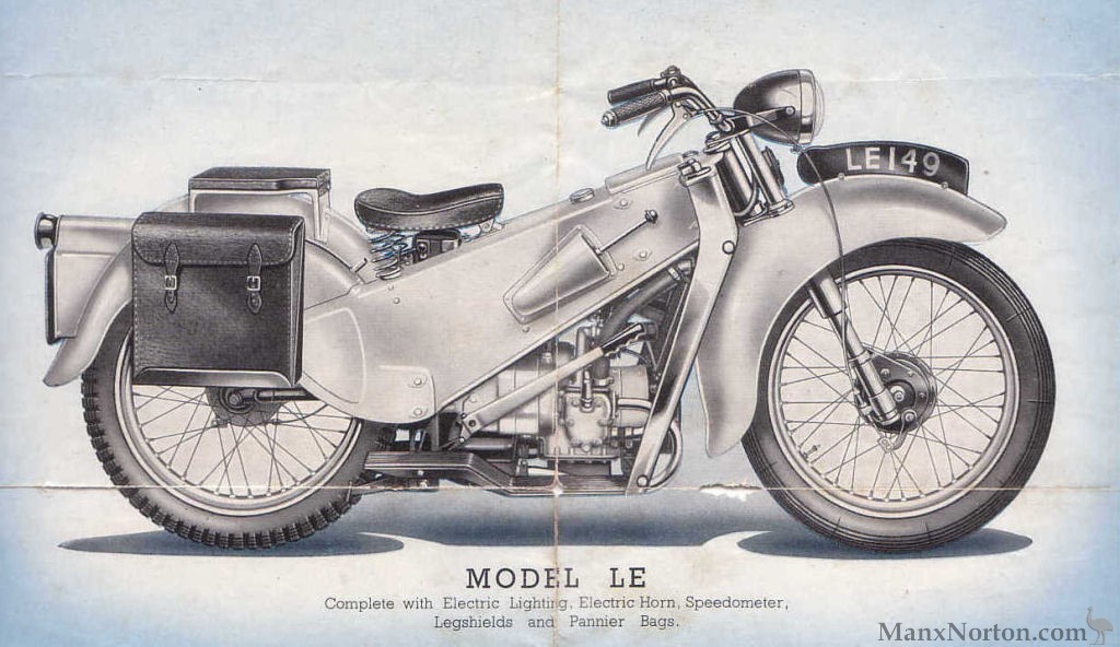
The Mark 1 was first produced after 20 years of development, and shown to the public for the first time at the Earls Court Show in 1948 as a bike that it was hoped would appeal to the public in general. It was the star of the show and attracted great interest. Consideration by the design staff was given to ease of use, quietness, weather protection, simple controls, economy and reliability. From these design constraints emerged the most radical British machine of the day.
Water-cooling was chosen for quietness with a horizontally opposed twin side valve for smoothness. The drive, via reduction gears, passed to a single plate clutch then to a three speed hand change gearbox. All of the engine, clutch and gearbox were built in a monoblock type of casting. Drive was taken from the gearbox to the rear wheel by a shaft drive, encased in a steel fabricated swing arm, this swing arm being controlled by coil springs and dampers. These springs were adjustable for load, using Veloce's own patent, within the rear mudguard. The main frame was of pressed steel and very substantial. Wheels were 19" x 3.5" and mounted on aluminium rims and covered with deep valanced mudguards. Legshields were fitted, made from polished aluminium, and had tops which held a speedo and switches for the lighting and ignition. Running board completed the weather protection. The centre stand was a combination of two side props, hence no effort was required to pull the bike on to the stand as both wheels remained on the floor. Pulling the start level flicked back this stand and the bike was ready to proceed. B.T.H. coil ignition was used, being driven from the front of the engine unit. This supplied a 6V D.C. current and HT for the ignition. A car type multi-jet carburettor by Amal was designed and used as a trouble-free form of petrol supply.
Various modifications were carried out during its manufacture, the most significant amendment being to the main bearings and big ends. The mains were ball and the big ends roller. It was found that in certain cases, when the machines were used on short journeys, condensation formed within the crankcase causing rusting of the bearings which inevitably led to failure. These were replaced by solid white metal units which involved some modifications to the con rods and crankshaft. The B.T.H. unit gave problems over a period. Carbon powder from the D.C. generator brushes, shorted out the ignition points and coil causing intermittent running. Different brush covers were employed to try to alleviate this problem. Over a period of time the multi-jet carburettor was reported as troublesome mainly as a result of blockages and icing in cold weather. However it was generally reported as a sound machine although under-powered. Veloce were quick to react and produced the Mk.II.
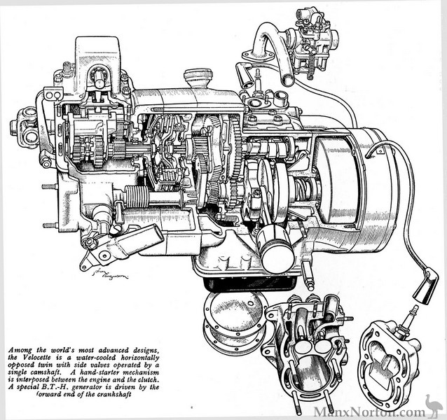
The drawing below shows the layout of the engine. Note the split crankshaft and the multi-jet carburettor.
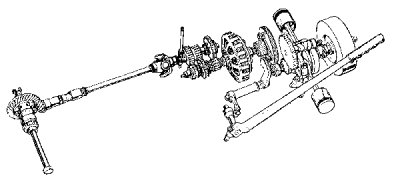
Here again we see the complete traction drive. Note the reduction from the crankshaft to the clutch (3 to 1) etc. This gave the required rev/power and helped to raise the final drive alignment with the centre of the 19" rear wheel.
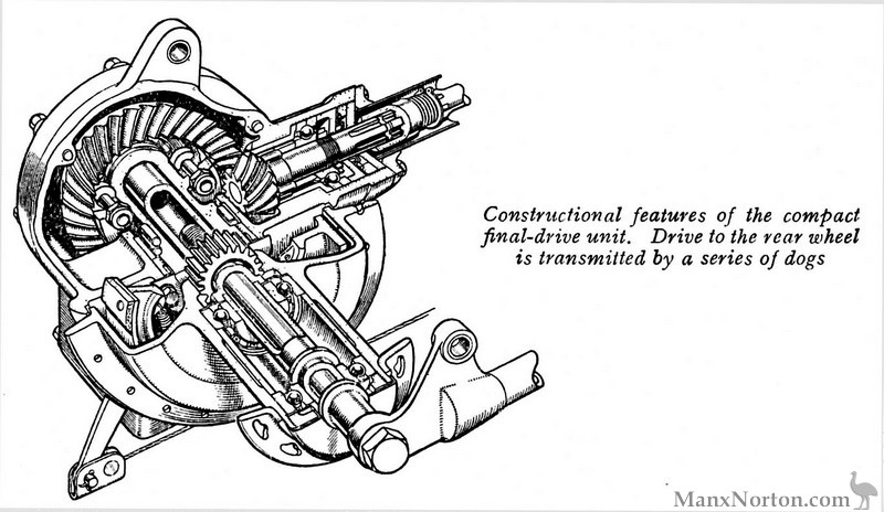
Transmission to the rear wheel was via a universal joint and spline to a crown wheel and pinion. See below.
Source: Alan Britch